Rotating spare tire lift system

a technology of spare tire and wheel, which is applied in the direction of spare wheel arrangement, vehicle components, load-carrying vehicle superstructure, etc., can solve the problem that full-size spare tire can be very difficult to lift, and achieve the effect of avoiding road debris

Active Publication Date: 2022-08-09
RIVIAN IP HLDG LLC
View PDF6 Cites 0 Cited by
  • Summary
  • Abstract
  • Description
  • Claims
  • Application Information

AI Technical Summary

Benefits of technology

[0002]A truck's spare tire is typically located behind the rear axle and mounted to the underside of the frame. A full-size spare tire can be very difficult to lift, and typically a winch is provided with which the user can lower the spare tire from the underside of the bed / frame of the truck bed. In such an arrangement, the spare is exposed to the elements. It would be advantageous to protect the spare tire from the environment and prevent awkward lifting postures.SUMMARY
[0003]The present disclosure is directed to systems for accessing a spare tire located underneath a cargo bed floor. For example, the spare tire can be easily lifted above the bed floor for removal. Furthermore, the operation of removing the spare tire is rotational from a recess in the bed that keeps the tire clean and away from road debris.

Problems solved by technology

A full-size spare tire can be very difficult to lift, and typically a winch is provided with which the user can lower the spare tire from the underside of the bed / frame of the truck bed.

Method used


Image

  • Rotating spare tire lift system
  • Rotating spare tire lift system
  • Rotating spare tire lift system

Examples


Embodiment Construction

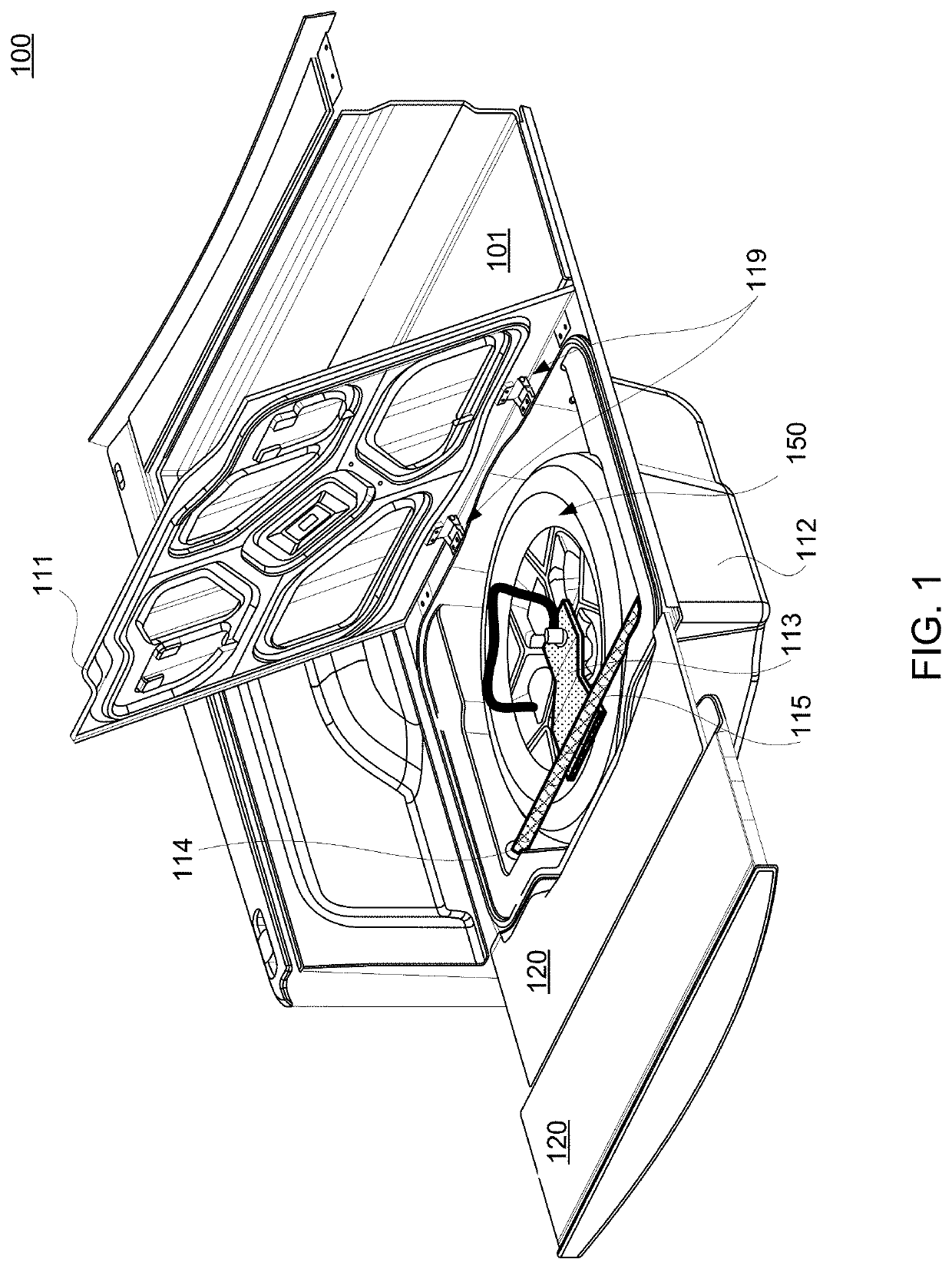
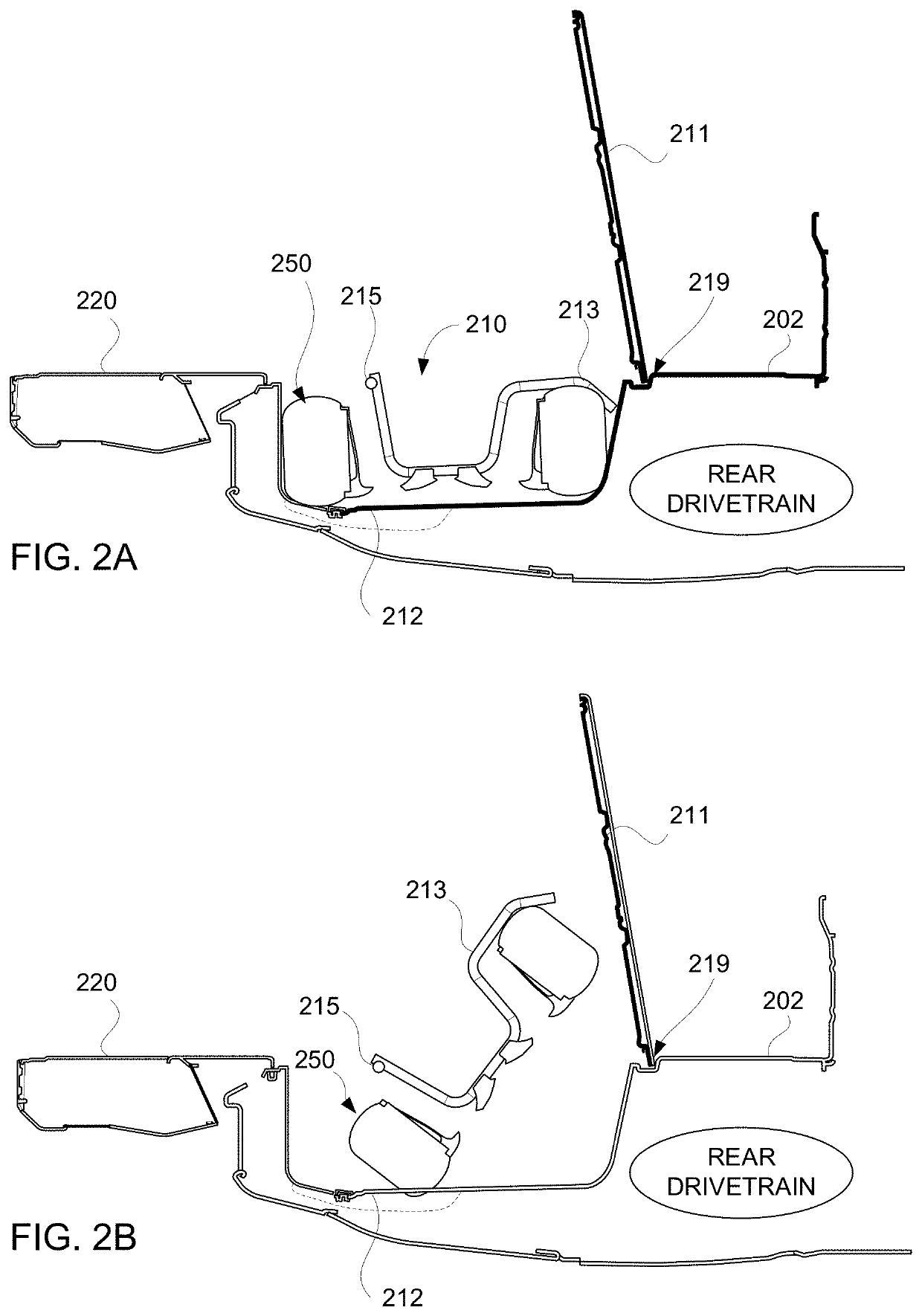
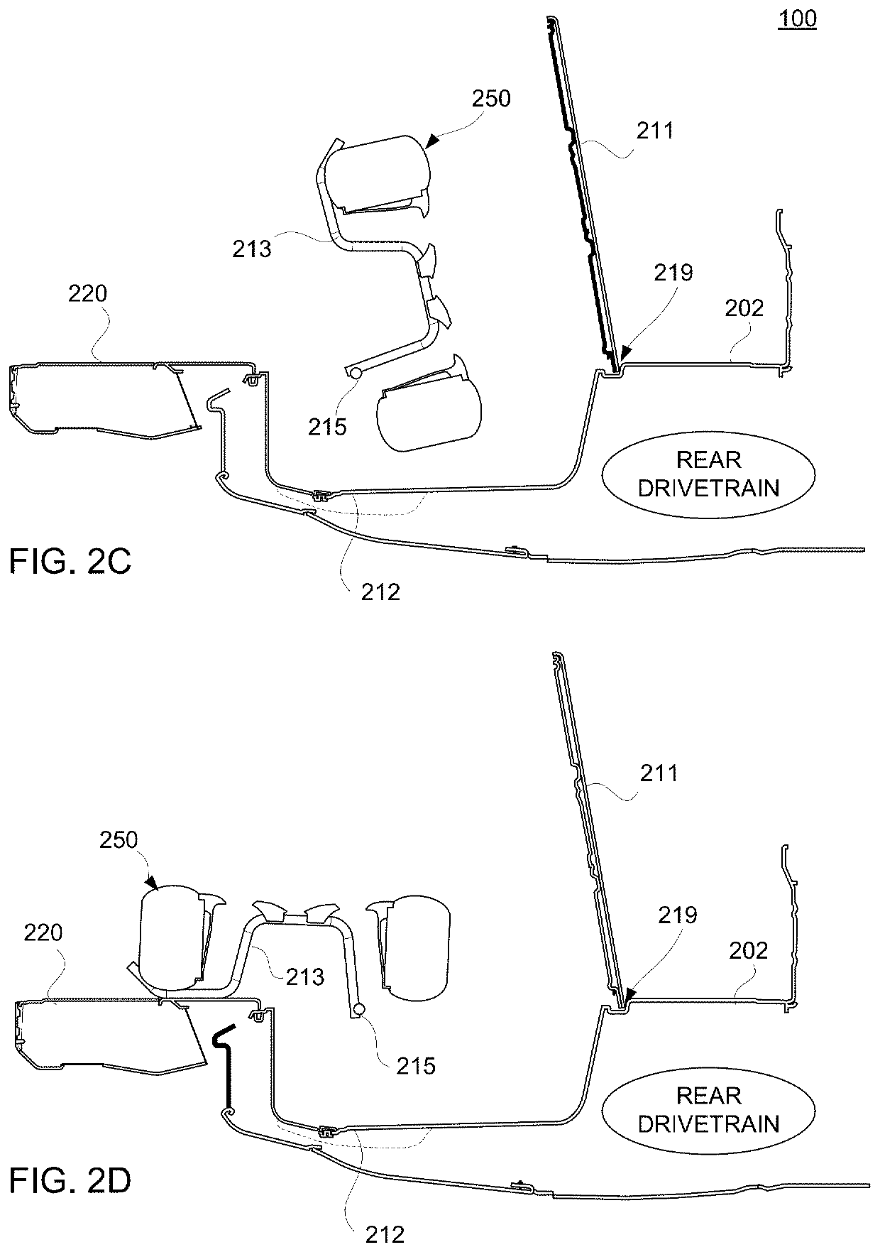
[0027]In some embodiments, the present disclosure is directed to systems for managing spare tire access in a vehicle bed. Regarding trucks, or other vehicles having a cargo bed, a full-size spare tire and rim (e.g., the assembly referred to herein as a “spare tire” or “wheel”) can be heavy (e.g., more than fifty pounds, eighty pounds) and cumbersome. In order to stow the spare tire under the frame, below the vehicle bed, there must be no components in the way to block access. Further, stowing a spare tire under a vehicle bed exposes the spare tire to the elements and mechanical damage from underneath the vehicle. The systems of the present disclosure allow the spare tire to be removed from above the bed, through an access panel in the bed. The weight of the full-size spare tire, which is very difficult to lift even by the strongest of individuals, is assisted using a mechanism that allows mechanical advantage to be employed. The systems of the present disclosure avoid the need for t...


PUM


Abstract

A system for accessing a wheel of a vehicle includes a support, a carrier, and a hinge joint. The support is affixed in a recess of a vehicle bed, and is positioned below the surface of the vehicle bed. The carrier is configured to be affixed to the wheel. When the carrier is affixed to the wheel, both the carrier and the wheel are accommodated in the recess and move as a substantially rigid body. The hinge joint couples the support and the carrier. The hinge joint has an axis substantially parallel to the ground and laterally across the vehicle bed. The carrier is capable of rotating about the hinge joint. The carrier and the wheel are capable of being rotated about the hinge joint out of the recess and onto the vehicle bed. One or more rotational elements may be included to affect rotational motion of the carrier.

Description

INTRODUCTION[0001]The present disclosure is directed towards a spare tire lift system, and more particularly towards a system for rotating a spare tire from under a vehicle bed.[0002]A truck's spare tire is typically located behind the rear axle and mounted to the underside of the frame. A full-size spare tire can be very difficult to lift, and typically a winch is provided with which the user can lower the spare tire from the underside of the bed / frame of the truck bed. In such an arrangement, the spare is exposed to the elements. It would be advantageous to protect the spare tire from the environment and prevent awkward lifting postures.SUMMARY[0003]The present disclosure is directed to systems for accessing a spare tire located underneath a cargo bed floor. For example, the spare tire can be easily lifted above the bed floor for removal. Furthermore, the operation of removing the spare tire is rotational from a recess in the bed that keeps the tire clean and away from road debris...

Claims


Application Information

Patent Timeline
Patent Type & Authority Patents(United States)
IPC IPC(8): B62D43/10B62D43/00B62D33/023
CPCB62D43/10B62D33/023B62D43/002B62D43/005B62D43/06
Inventor GRIFFITH, ERIC SCOTT
Owner RIVIAN IP HLDG LLC
Why Eureka
Try Eureka