Method and apparatus for lateral well drilling with enhanced capability for clearing cuttings and other particles

a technology of lateral well drilling and cuttings, which is applied in the direction of directional drilling, artificial islands, borehole/well accessories, etc., can solve the problems of blockage or obstruction of internal passages within the apparatus, difficulty in avoiding entry of cuttings into the lateral opening, etc., to facilitate the upward flow of liquid, reduce the hydrostatic head, and boost the upward flow

Active Publication Date: 2009-10-15
LATJET SYST
View PDF13 Cites 6 Cited by
  • Summary
  • Abstract
  • Description
  • Claims
  • Application Information

AI Technical Summary

Benefits of technology

[0019]Thus, according to the invention, a pathway is provided for the pressurized gas or emulsion, from a compressor or pump on the surface, down through the well through the interior of the outer tubing, and through the hole or holes in the sheath and into the elbow of the kick-off shoe, where the fluid will exit in the above described manner, for clearing cuttings and other particles from the vicinity of the lateral opening of the shoe, and for preventing entry thereof into the opening so as to interfere with movement of the flexible tubing therein. The sectional size of the elbow will be sufficient for accommodating the flexible tubing and also the pressurized gas or emulsion.
[0020]As noted above, the pressurized gas, e.g., compressed air, or emulsion, exiting the shoe can be used for clearing cuttings from the vicinity of the lateral opening, and also for reducing the hydrostatic head, in this latter regard, either alone, or in combination with other elements for that purpose. In my prior patent, the lower end of the outer tubing is configured as a jet tube, including one or more air jets for discharging pressurized air carried in the outer tubing, into the well, which air will then rise and carry liquid present in the lower portion of the well casing upwardly to the surface. In the present invention, this is at least mostly replaced by discharging of the pressurized gas or emulsion from the region around the lateral opening of the shoe, and / or discharge from the lateral opening itself. Supplemental arrangements for discharge of pressurized gas, e.g., air, or emulsion, can also be utilized, as desired or required. For example, outlets or nozzles can be provided at intervals along the length of a selected portion of the outer tubing, for discharging pressurized gas or emulsion therefrom, for boosting the upward flow of the cuttings and other particles, particularly abrasives, and liquid through the well. Such additional outlets or nozzles can also facilitate the upward flow of the liquid and cuttings and other particles within the well when the hydrostatic head is sufficiently great to prevent discharge of the gas or emulsion, e.g., air, through the lateral opening and related outlets. Further in this regard, by discharging some of the pressurized gas or emulsion at higher regions within a well, the pressure of the gas or emulsion in and discharged from the lower region, e.g., the lateral opening of the kick-off shoe, will be at a lower pressure. This can be an advantage, as prior to initiation of the introduction of the pressurized gas or emulsion, the hydrostatic head will be present within the outer tubing of the down-hole apparatus. Then, as the pressurized gas or emulsion is introduced into this tubing, the liquid therein will be displaced to the annulus between the inner surface of the well casing and the outer surface of this tubing, so as to increase the height of the column of liquid in the annulus, thereby making it harder to lift to the surface. By providing additional outlets or nozzles at one or more higher elevations within the well, the pressurized gas or emulsion introduced into the annulus will be better able to lift the liquid at that level or levels for reducing the hydrostatic head, and importantly, the required pressure in the vicinity of the kick-off shoe for removing the hydrostatic head from that location. The ability to have a lower pressure at the lower region within the well is advantageous particularly in wells containing fine particulates, such as, but not limited to, coal bed methane, as it reduces the occurrence or possibility of those particulates being forced into the formation by a higher pressure. This is also advantageous if the well produces a large amount of liquid or the apparatus has been idle for a sufficient time for a tall hydrostatic head to form, particularly if so large that not enough pressure can be developed by the compressor apparatus for removing the head from the region of the kick-off shoe alone.

Problems solved by technology

However, in the latter instance at least, the pressure and forcefulness of the fluid, cuttings and other particles exiting the lateral passage can be relatively great, making it difficult to avoid entry thereof into the lateral opening.
Additionally, as the down hole apparatus is lowered into a well, and at other times when in the well, it may be subject to entry and accumulation of particulates and other solid matter that may be present in the well, so as to possibly result in blockage or clogging of internal passages within the apparatus, in the principal example discussed above, the lateral opening and elbow of the kick-off shoe.

Method used


Image

  • Method and apparatus for lateral well drilling with enhanced capability for clearing cuttings and other particles
  • Method and apparatus for lateral well drilling with enhanced capability for clearing cuttings and other particles
  • Method and apparatus for lateral well drilling with enhanced capability for clearing cuttings and other particles

Examples


Embodiment Construction

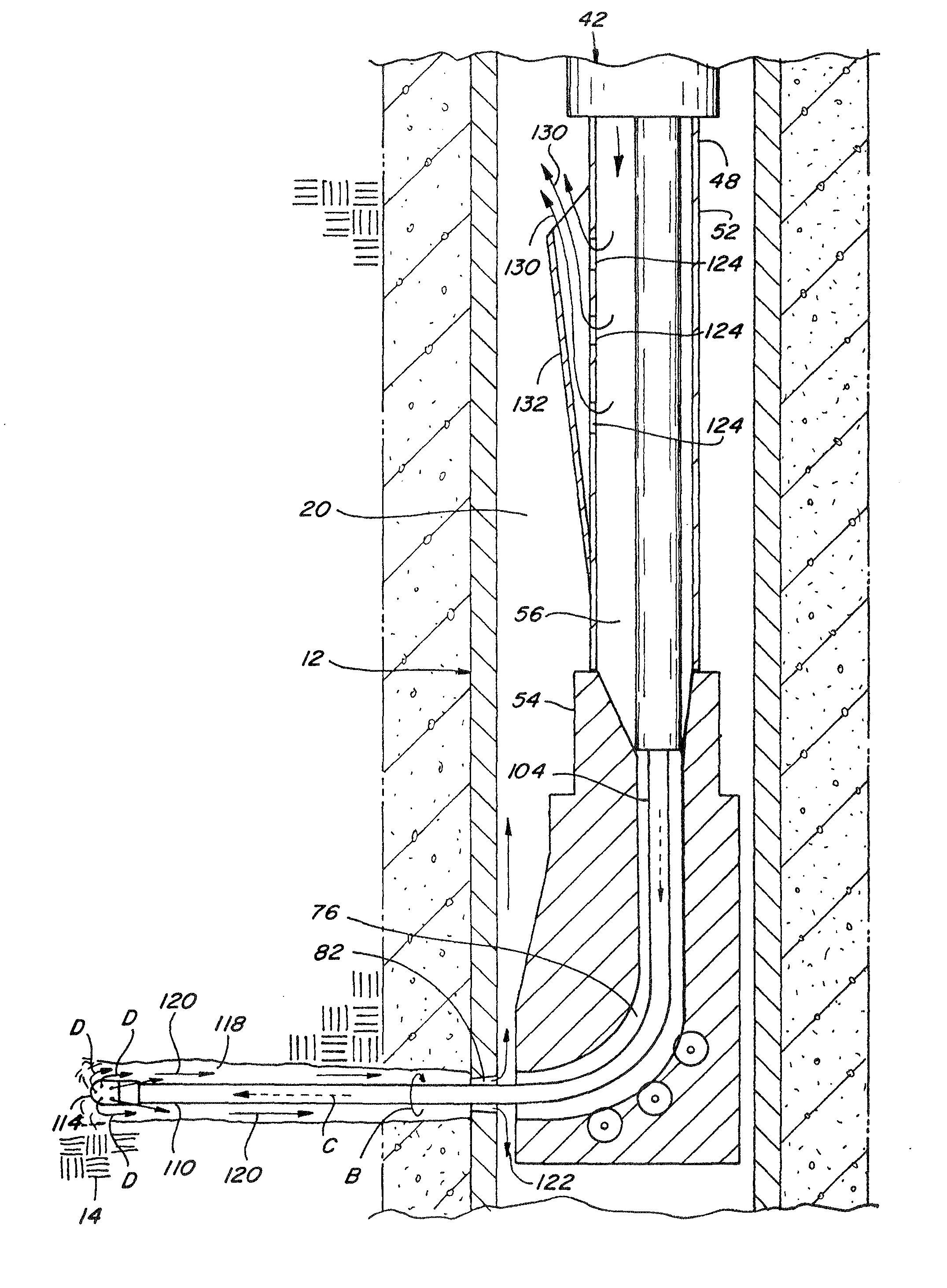
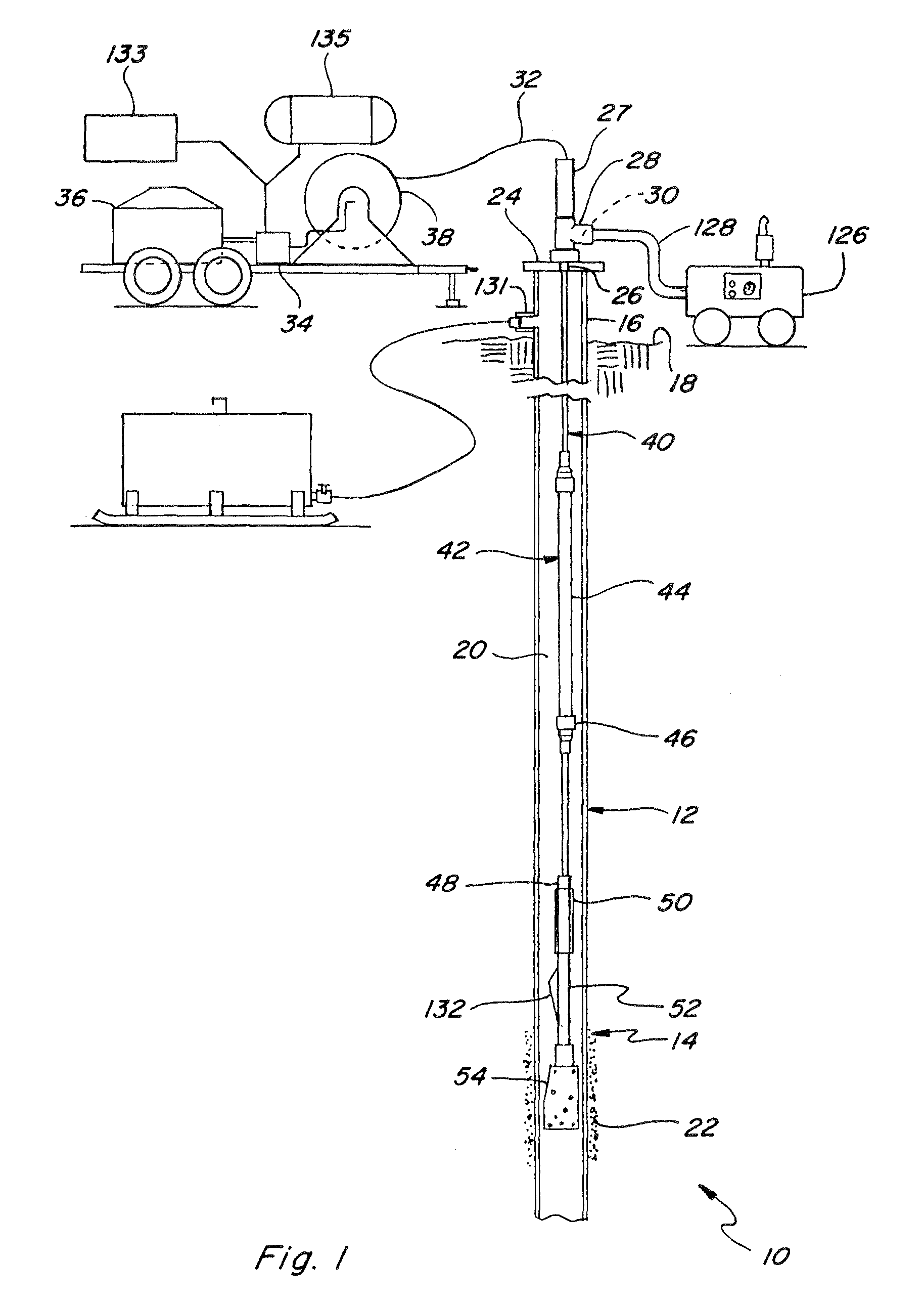
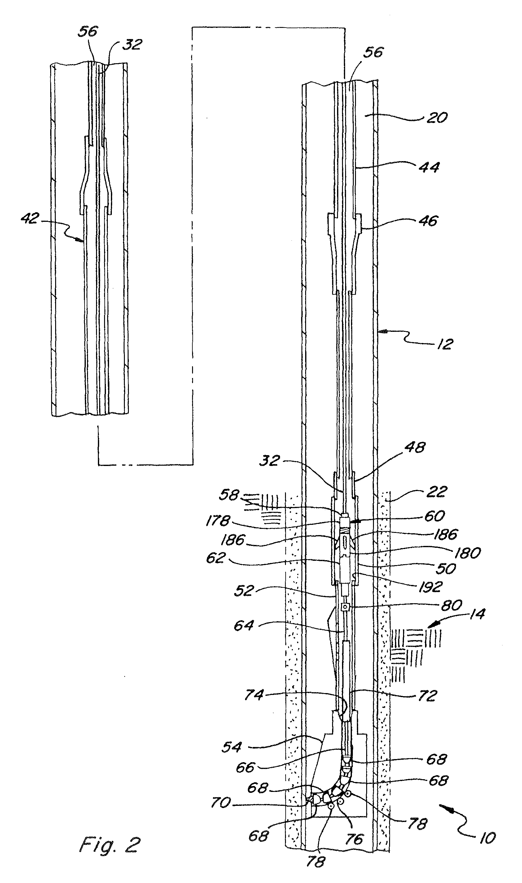
[0052]FIGS. 1 and 2 show apparatus 10 constructed and operable according to my previous invention of Peters U.S. Pat. No. 6,283,230, for penetrating a well casing 12 and surrounding earth strata 14. As explained in that patent, well casing 12 consists of steel piping extending from a well head 16 on or near the earth's surface 18 downwardly through strata 14 into a formation therein which hopefully contains oil and / or gas. Well casing 12 is of conventional construction defining an interior cavity or passage 20 of from between about 4 to about 8 inches in diameter and from several hundred to several thousand feet in depth. Cement or other material 22 is typically located around well casing 12 to hold it in place and prevent leakage from the well. Well head 16 includes a cap 24 having an opening 26 therethrough communicating passage 20 with a conventional oil saver device 27, and a tee 28 including an access port 30.

[0053]Apparatus 10 includes a quantity of flexible tubing 32 adapted ...


PUM


Abstract

Apparatus for clearing particles from a lateral drilling operation in strata beside a well. The drilling apparatus is part of a down hole unit and is configured for extending from a lateral opening of the unit into a lateral passage in the adjacent strata, and the operation of the drilling apparatus discharges particles from the lateral passage toward the lateral opening. The invention deflects or redirects the particles discharged from the lateral passage, away from the lateral opening, to prevent clogging or blocking of an internal passage or elbow through the down hole unit, using a pressurized fluid such as a gas or an emulsion. The pressurized fluid can also be configured for carrying the particles upwardly through the well to the surface, and for reducing or removing a hydrostatic head in the well.

Description

[0001]This application claims the benefit of U.S. Provisional Patent Application Ser. No. 61 / 044,552, filed Apr. 14, 2008.TECHNICAL FIELD[0002]This invention relates generally to methods and apparatus for penetrating a side of a well casing and / or drilling into earth strata beside or surrounding the well casing, or directly into the strata in the absence of a casing, and more particularly, to an improved method and apparatus for drilling into the casing and surrounding earth strata, which enhances the clearing of particles including cuttings and abrasives, if used, from the drilling, and reduces build up of the particles in and around the apparatus, for improved operation.BACKGROUND ART[0003]The disclosure of Peters U.S. Pat. No. 6,283,230 entitled METHOD AND APPARATUS FOR LATERAL WELL DRILLING UTILIZING A ROTATING NOZZLE, issued Sep. 4, 2001, as well as the disclosures of my co-pending U.S. patent application Ser. No. 12 / 350,707 and U.S. Provisional Patent Application Ser. Nos. 61 / ...

Claims


Application Information

Patent Timeline
Patent Type & Authority Applications(United States)
IPC IPC(8): E21B7/08E21B7/04E21B43/11E21B7/18
CPCE21B7/061E21B21/14E21B7/18E21B7/068
Inventor PETERS, JASPER N.
Owner LATJET SYST
Why Eureka
Try Eureka