Material roll and method for manufacturing material roll

a technology of material roll and roll, applied in the field of material roll, can solve the problems of cumbersome work, scratching or contamination of sheet material, and achieve the effect of improving durability

Inactive Publication Date: 2011-03-10
NITTO DENKO CORP
View PDF21 Cites 5 Cited by
  • Summary
  • Abstract
  • Description
  • Claims
  • Application Information

AI Technical Summary

Benefits of technology

[0023]According to the present invention, it is possible to make lifting be hardly generated between the base films and the optical film and to improve the durability in a high-temperature environment by setting the adhesive power B of the first pressure-sensitive adhesive layer at the interface on the optical film side to be larger than the adhesive power A of the first pressure-sensitive adhesive layer at the interface on the first base film side and by setting the adhesive power C, D of the second pressure-sensitive adhesive layer to be larger than the above adhesive power A and winding the optical film so that the second base film side having a larger adhesive power is in the inside.

Problems solved by technology

The above packaging work is a necessary work because the film maker and the panel processing manufacturer are located at different positions; however, the work is cumbersome and also raises a problem in that scratches or contaminations are likely to generate in the pieces of sheet material at the time of transportation or the like.

Method used


Image

  • Material roll and method for manufacturing material roll
  • Material roll and method for manufacturing material roll
  • Material roll and method for manufacturing material roll

Examples


example 1

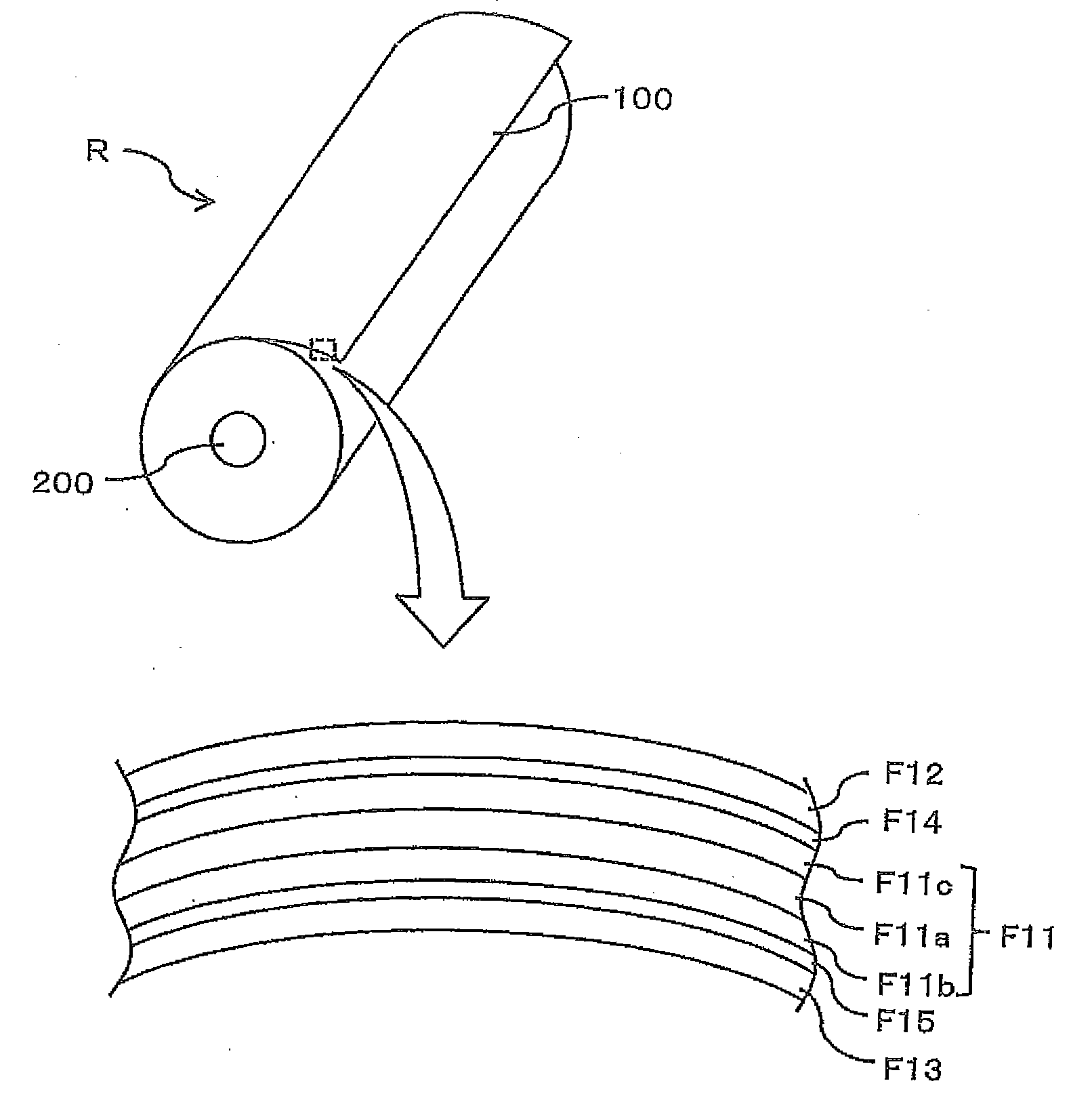
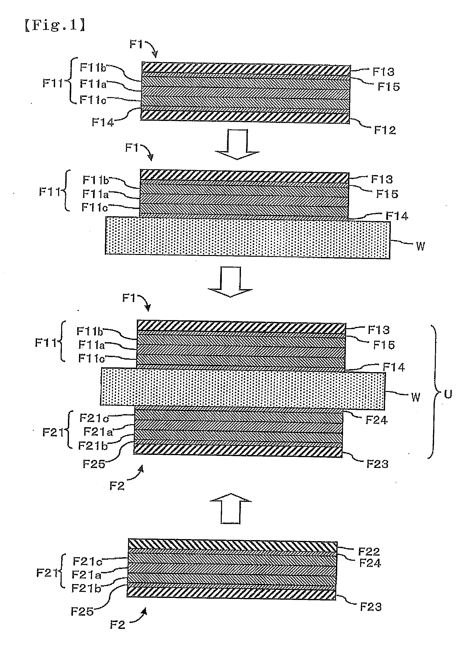
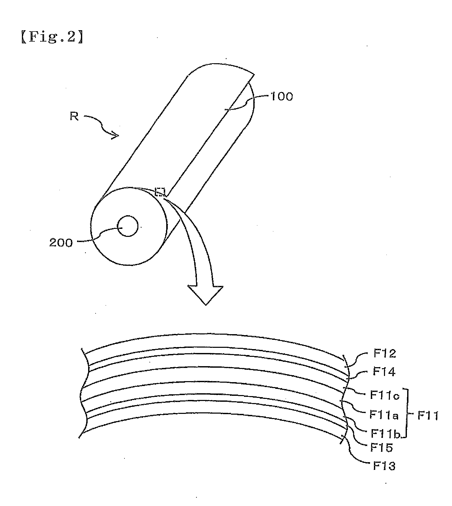
[0045]In Example 1, a sheet material was used in which a release liner “MRF38” (manufactured by Mitsubishi Resin Co., Ltd.) was bonded as a first base film on a pressure-sensitive adhesive layer (first pressure-sensitive adhesive layer) of a polarizing film “SEG1423” (manufactured by Nitto Denko Corporation) having the pressure-sensitive adhesive layer attached thereto and serving as an optical film, and a surface protecting film “RP-300” (manufactured by Nitto Denko Corporation) was bonded as a second base film on a surface opposite to the pressure-sensitive adhesive layer.

[0046]The first base film is made of polyethylene terephthalate and has a thickness of 38 μm. The second base film is a film also formed of polyethylene terephthalate in the same manner as the first base film and having a thickness of 38 μm and, on the bonding surface for bonding to the optical film, a pressure-sensitive adhesive layer (second pressure-sensitive adhesive layer) made of acrylic-based pressure-sens...


PUM

PropertyMeasurementUnit
thicknessaaaaaaaaaa
thicknessaaaaaaaaaa
humidityaaaaaaaaaa

Abstract

Provided are a material roll and a method for manufacturing the material roll in which lifting between base films and an optical film is hardly generated. Provided is a material roll (R), wherein a first base film (F12), a first pressure-sensitive adhesive layer (F14), an optical film (F11), a second pressure-sensitive adhesive layer (F15) and a second base film (F13) are wounded together in a manner that said layers are laminated in said order from outer side. An adhesive power A of the first pressure-sensitive adhesive layer (F14) at an interface on the first base film (F12) side, an adhesive power B of the first pressure-sensitive adhesive layer (F14) at an interface on the optical film (F11) side, an adhesive power C of the second pressure-sensitive adhesive layer (F15) at an interface on the optical film (F11) side, and an adhesive power D of the second pressure-sensitive adhesive layer (F15) at an interface on the second base film (F13) side satisfy the relationships A<B and A<C<D. Lifting between base films (F12, F13) and optical film (F11) can be made unlikely to generate by winding the optical film (F11) in a manner that the second base film (F13), that has greater adhesive power is in an inside.

Description

TECHNICAL FIELD[0001]The present invention relates to a material roll made by winding a long optical film having a first base film disposed on a first surface with a first pressure-sensitive adhesive layer interposed therebetween and having a second base film disposed on a second surface with a second pressure-sensitive adhesive layer interposed therebetween, as well as to a method for manufacturing the material roll.BACKGROUND ART[0002]As an example of optical display units mounted on liquid crystal display devices or the like, there is an optical display unit having a structure such that an optical sheet piece including an optical film such as a polarizing film is bonded onto one surface or both surfaces of a display substrate. Conventionally, as a method for manufacturing such an optical display unit, there is known a method including a step of manufacturing pieces of sheet material by feeding a sheet material from a material roll made by winding the sheet material in which a rel...

Claims


Application Information

Patent Timeline
Patent Type & Authority Applications(United States)
IPC IPC(8): B32B27/36B32B37/12
CPCY10T428/1471Y10T428/14G02B5/3083B32B7/12G02B5/3033Y10T156/1089G02F2202/28B32B27/36B32B7/06Y10T156/1092Y10T428/24942B32B27/08B32B23/08B32B23/20B32B27/28B32B27/302B32B27/304B32B27/306B32B27/308B32B27/32B32B27/34B32B27/365B32B2250/24B32B2270/00B32B2307/308B32B2307/412B32B2307/42B32B2307/50B32B2307/7246B32B2307/748B32B2457/20B32B2457/202Y10T428/31786
Inventor TAKEDA, KENTAROUOOISHI, MICHIHITO
Owner NITTO DENKO CORP
Why Eureka
Try Eureka