Two-stage transmission for electrically driven vehicle

a transmission and electrical drive technology, applied in mechanical actuated clutches, transportation and packaging, gearing, etc., can solve the problem of difficulty for even the electric motor to keep a high efficiency over an overall vehicle speed range, and achieve the effect of reducing transmission shock and preventing transmission shock

Active Publication Date: 2022-08-09
UNIPRES CORP
View PDF5 Cites 1 Cited by
  • Summary
  • Abstract
  • Description
  • Claims
  • Application Information

AI Technical Summary

Benefits of technology

[0010]In an intermediate state that the dog clutch and the friction clutch are not engaged when shifting between the first speed mode and the second speed mode, by disposing the one-way clutch, the instantaneous rotation drop in the output side and the transmission shock can be prevented. By using the ratchet-type one-way clutch, the dog clutch can instantaneously become the engagement state when switching from the friction clutch to the dog clutch (speed reduction). In the normal engagement operation of the dog clutch, the waiting operation for completing the engagement is needed. In a case of using the one-way clutch, since this waiting operation is not needed, further reduction of the transmission shock can be realized.

Problems solved by technology

It is difficult for even the electric motor to keep a high efficiency over an overall vehicle speed range.

Method used


Image

  • Two-stage transmission for electrically driven vehicle
  • Two-stage transmission for electrically driven vehicle
  • Two-stage transmission for electrically driven vehicle

Examples


Embodiment Construction

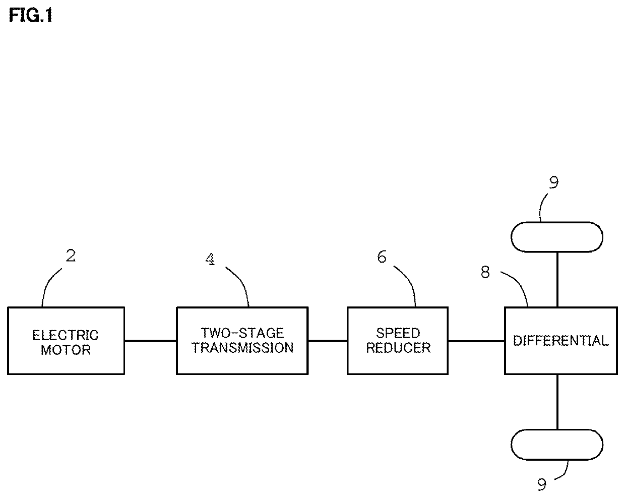
[0022]FIG. 1 is a schematic view showing a wheel driving train of an electric vehicle, which is used in a two-stage transmission for an electrically driven vehicle of the first embodiment according to the present invention. Reference numerals 2, 4, 6, 8 and 9 indicate an electric motor for running, a two-stage transmission, a speed reducer, a differential and wheels, respectively. The speed reducer 6 and gears which are engaged with the speed reducer 6 are received in a casing and the speed reducer 6 is disposed for reducing high rotational number in the electric motor 2 to the rotational number appropriate for the running by the wheels 9. In a case of the normal electric vehicle which does not include the two-stage transmission 4, a value of the reduction ratio in the speed reducer 6 is set to about eight. In normally used low vehicle speed driving, this value is suitable for operating the electric motor 2 in a high efficient rotational number range. However, in a case that this se...


PUM


Abstract

The present invention relates to a two-stage transmission for an electrically driven vehicle including a dog clutch and a friction clutch, and an object of the present invention is to prevent a torque drop when shifting gears. The two-stage transmission for the electrically driven vehicle includes a planetary gear mechanism (12), a dog clutch (28), a friction clutch (30), an armature (26) to switch between the dog clutch (28) and the friction clutch (30), and an electromagnetic coil (31) to drive the armature (26). In the dog clutch (28) and the friction clutch (30), the coupling relationship among the rotational elements of the planetary gear mechanism (12) is set such that the dog clutch (28) is fastened and the friction clutch (30) is not fastened in speed reduction (the first speed), and the dog clutch (28) is not fastened and the friction clutch (30) is fastened in speed increase (the second speed). To prevent the torque drop when shifting the gears, a ratchet-type one-way clutch (50) is disposed such that a rotational phase position of the ratchet-type one-way clutch (50) is coincident with that of the dog clutch (28). When shifting from the second speed to the first speed, since the rotational phase of the dog clutch (28) is adjusted by the ratchet-type one-way clutch (50), the shifting is instantaneously completed without waiting operation for the phase adjustment, resulting in preventing a transmission shock.

Description

TECHNICAL FIELD[0001]The present invention relates to a two-stage transmission for an electrically driven vehicle such as an electric vehicle (EV) and a hybrid vehicle.BACKGROUND ART[0002]In an electric vehicle (EV) whose power is obtained from an electric motor, such as a hybrid vehicle whose power is obtained from switching between an engine and the electric motor and a vehicle which is run by only the driving power from the electric motor, a power transmission from the electric motor to an axle side is normally performed by providing with only a speed reducer in which a rotational number of the electric motor is reduced to that of the axle whose value is appropriate for running, without providing with another transmission. This is because the electric motor enables to generate a driving torque from a low rotational number range, have a wide rotational range which can be used for running and have a simple structure which is an important sales point of the electric vehicle (EV).[00...

Claims


Application Information

Patent Timeline
Patent Type & Authority Patents(United States)
IPC IPC(8): F16H3/54F16D21/00
CPCF16H3/54F16D21/00F16H2200/0021F16H2200/0034F16H2200/2005F16H2200/2033F16H2200/2064F16H2200/2066F16H2200/2082F16H2200/2094F16H2200/2097F16H3/44F16H3/006F16H2200/2038F16H2200/2035F16H2061/0429F16H61/04F16H2061/0474
Inventor SHIROSAKI, RYOSUZUKI, RYOSUKENEZU, HIDEYUKIOONO, YUTAFURUKAWA, KENTARO
Owner UNIPRES CORP
Why Eureka
Try Eureka