
Cooling device for battery cells assembled into a module

a battery cell and cooling device technology, applied in cell sealing materials, cell components, cell cases/jackets, etc., can solve the problems of increasing the risk of temperature control fluid escaping from the flow channel, mechanical damage to the battery cells and the cooling device insert, and affecting the efficiency of the cooling devi

Active Publication Date: 2022-08-09
KREISEL ELECTRIC GMBH & CO KG
View PDF16 Cites 0 Cited by
  • Summary
  • Abstract
  • Description
  • Claims
  • Application Information

AI Technical Summary

Benefits of technology

The invention relates to a carrier for battery cells that have a cooling device embedded within them. The battery cells are securely fitted in the carrier and can withstand high levels of pressure without moving or pivoting. The cooling device is designed to compensate for any variations in the size of the battery cells. The design also helps to improve the assembly process by eliminating the need for pre- sorting the battery cells before they are inserted into the carrier. The exposed parts of the battery cells are embedded within a casting compound, which ensures stability and secure fitting in the carrier.

Problems solved by technology

A disadvantage of this, however, is that due to the insert, which is preferably made of high-strength and dimensionally stable plastics, and the support ribs, the battery cells are fixed in the receptacles, so that the fluctuations in the cell geometry or the deformations of the cell contour, which occur due to the electrical and thermal operating state, are not compensated for and as a result both the battery cells and the cooling device insert can be mechanically damaged.
A further disadvantage is that in this type of cooling device, the cylindrical battery cells, which are in direct contact with the temperature control fluid in the area of the negative cell pole, must be contacted either via a conductive temperature control fluid or via an electrical conductor which protrudes through the opening in the holder and makes contact with the negative cell pole.
In addition, there is an increased risk of temperature control fluid escaping from the flow channel due to changing cell contours, because the fit and thus the gap between the holder and the battery cell used in it can change as a result of the geometric changes occurring during operation in such a way that the temperature control fluid under pressure escapes from the flow channel through the openings.
In particular, the membrane is applied to the cell bottom in such a way that any air mass lying between the membrane and the cell bottom, which air mass might act as an additional insulator and impairing the efficiency of the cooling device, is largely displaced by the membrane.
Due to different electrical operating conditions as well as due to different constructive designs of the module, module areas can form which are subject to different thermal loads, which can subsequently promote the formation of undesired heat accumulation zones and reduce the overall performance of such modules.

Method used


Image

  • Cooling device for battery cells assembled into a module
  • Cooling device for battery cells assembled into a module

Examples


Embodiment Construction

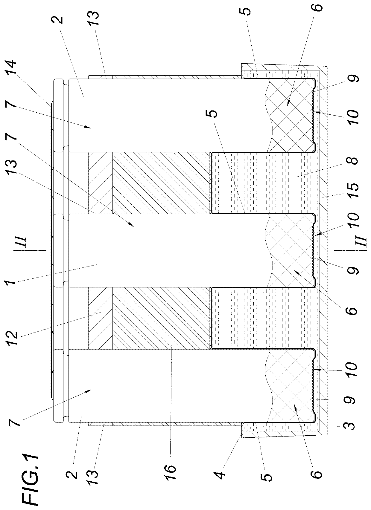
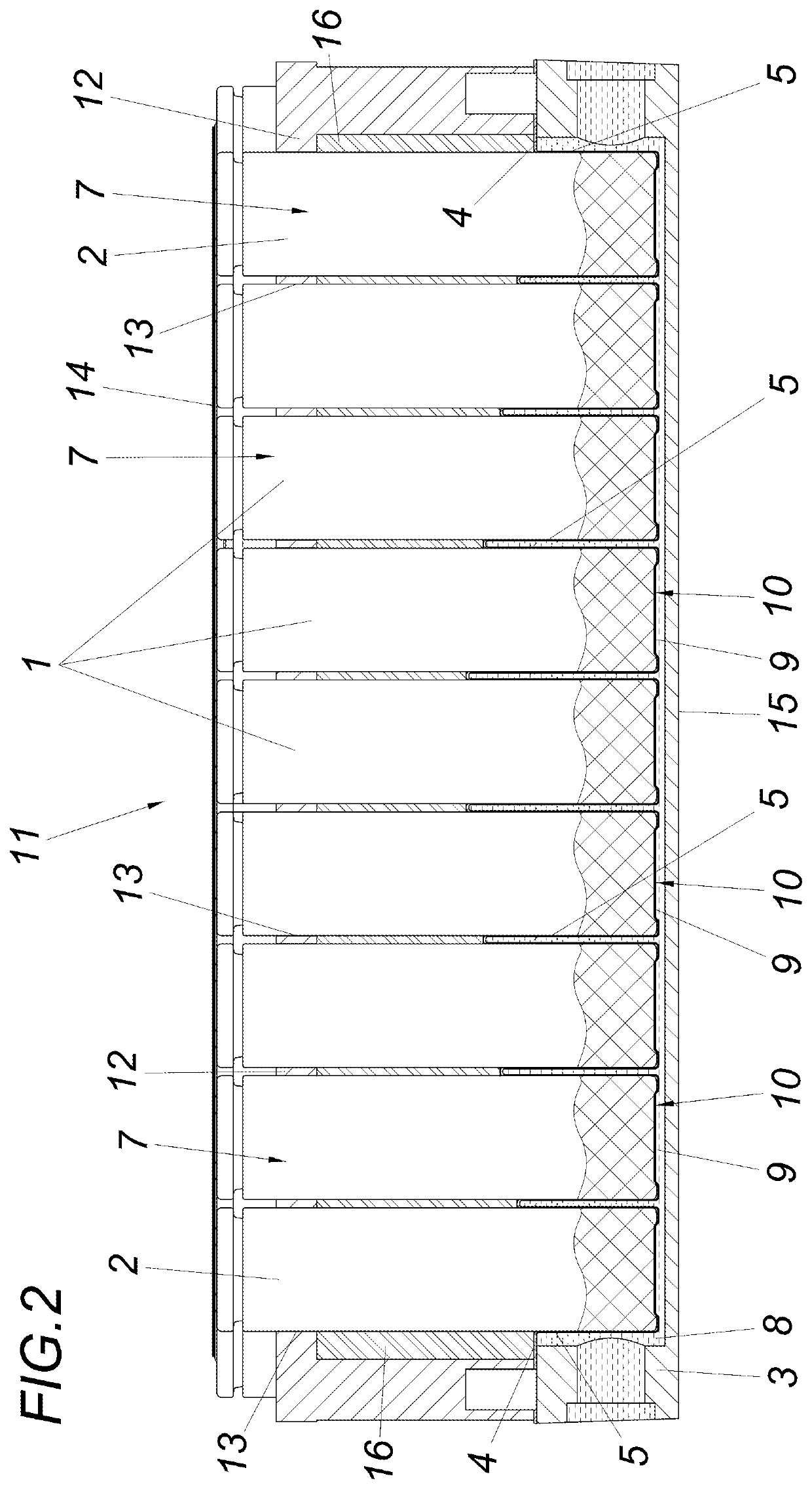
[0004]The invention is therefore based on the task of designing a cooling device of the type described above in such a way that the battery cells can be reliably accommodated with low manufacturing costs and high performance with respect to temperature control, without having to take into account the manufacturing tolerances of the battery cells in advance.

[0005]The invention solves this problem in that the receptacles form a fluid-tight membrane enclosing the end portion of the battery cells, which membrane is designed to be deformable to compensate for the tolerances of the individual battery cells and rests against the bottom of the cells when the flow channel is filled.

[0006]As a result of these features, reliable tolerance compensation can be provided in the event of operationally induced changes in geometry, both with regard to cell contour variations and with regard to the relative position of the cells held in the receptacles with respect to one another, while the membrane b...


PUM

PropertyMeasurementUnit
pressureaaaaaaaaaa
thermal resistancesaaaaaaaaaa
temperatureaaaaaaaaaa

Abstract

A cooling device for battery cells assembled to form a module, having a base body and an insert which has receptacles for an end portion of the battery cells with recesses in the cell head. The insert together with the base body delimits a flow channel for a temperature control fluid A cooling device of this type permits operationally reliable accommodation of the battery cells with low manufacturing costs and high temperature control performance, without having to take manufacturing tolerances into account in advance. The receptacles form a fluid-tight membrane which encloses the end portion of the battery cells, which membrane is deformable for tolerance compensation of the individual battery cells and rests against the cell bottom when the flow channel is filled.

Description

TECHNICAL AREA[0001]The invention relates to a cooling device for battery cells assembled to form a module, comprising a base body and an insert, which insert is having receptacles for an end portion of the battery cells excepting the cell head, whereby the insert together with the base body is delimiting a flow channel for a temperature control fluid.STATE OF THE ART[0002]In particular in connection with battery modules comprising cylindrical battery cells, cooling devices are known from the prior art (DE 102006010063 A1), which have a base body and an insert with receptacles for the individual battery cells, whereby the base body together with the insert is defining a flow channel for a temperature control fluid. The receptacles are such that they surround an end portion of the battery cells on the circumferential side, excepting the cell head in each case. To enable dissipation of the heat generated by the battery cells during operation, DE 102006010063 A1 states that only the ce...

Claims


Application Information

Patent Timeline
Patent Type & Authority Patents(United States)
IPC IPC(8): H01M10/6556H01M10/613H01M10/6567H01M50/204H01M50/183H01M10/643H01M10/6557
CPCH01M10/6556H01M10/613H01M10/6567H01M50/183H01M50/204H01M10/643H01M10/6557Y02E60/10H01M10/625H01M10/627H01M50/20
Inventor MENZL, KILIANBERGER, BERNHARD MAXIMILIANPUMSLEITNER, JOHANNESKREGL, PHILIPPDOBUSCH, PETER
Owner KREISEL ELECTRIC GMBH & CO KG
Learn More