
Circuit based unmanned aerial vehicle

a technology of unmanned aerial vehicles and circuits, applied in aircrafts, influencers using rotating members, transportation and packaging, etc., can solve problems such as unsafe use of a variety of methods for close public interaction

Active Publication Date: 2022-08-16
CARNEGIE CAMERON
View PDF26 Cites 1 Cited by
  • Summary
  • Abstract
  • Description
  • Claims
  • Application Information

AI Technical Summary

Benefits of technology

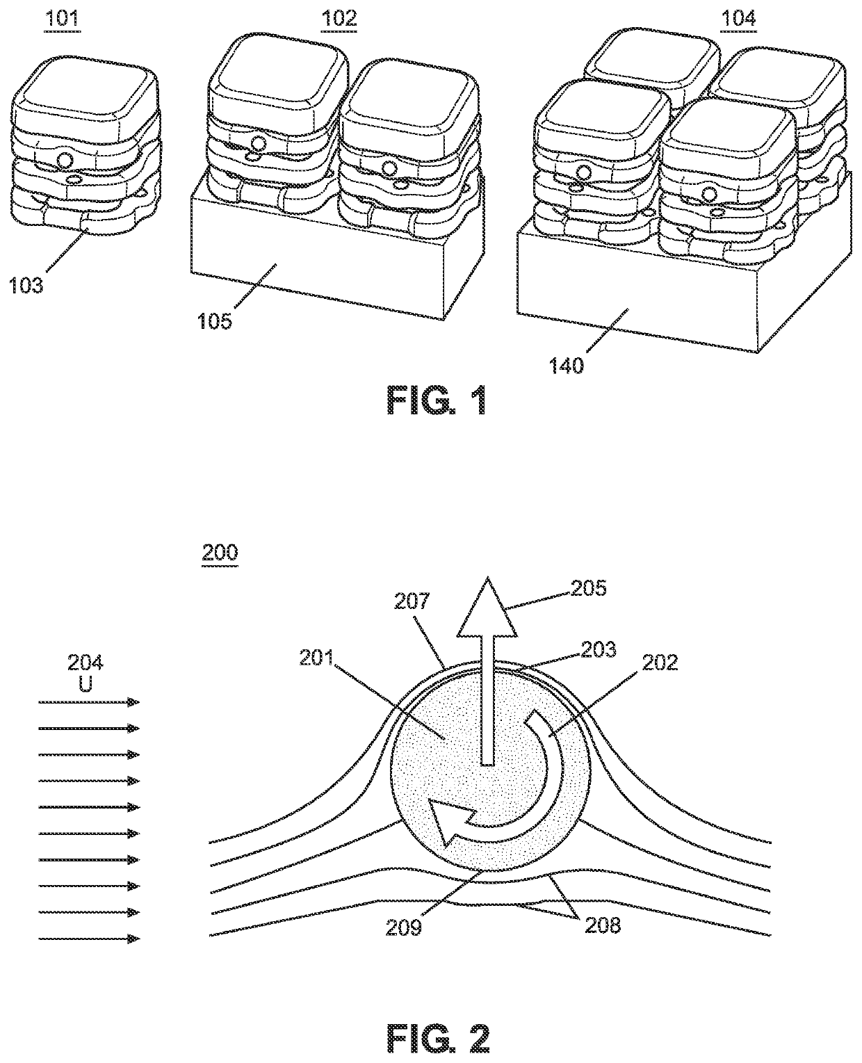
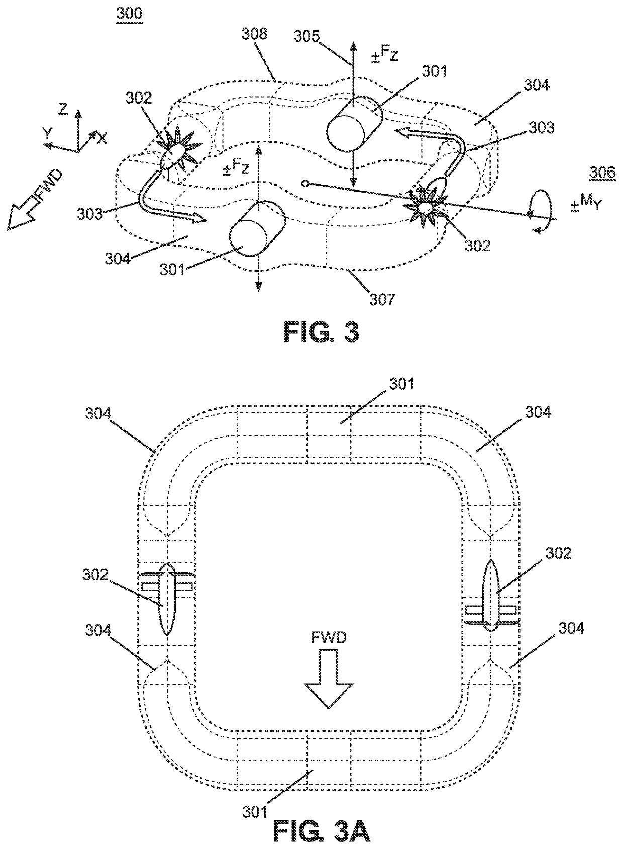
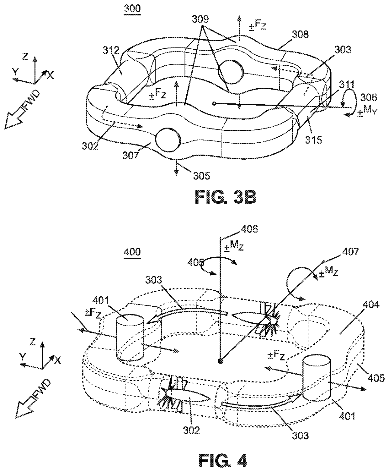
This patent describes a new design for a quadcopter drone that includes pairs of vertical cylinders that provide bidirectional force for lateral movement, balance, and yaw control. The drone also has slidable air vents that allow for external air to flow into the fan ducts, which helps with navigation. The technical effects of this design are improved efficiency, stability, and control for the drone during flight.

Problems solved by technology

However, current UAV designs use a variety of methods that are unsafe for close public interaction.

Method used


Image

  • Circuit based unmanned aerial vehicle
  • Circuit based unmanned aerial vehicle
  • Circuit based unmanned aerial vehicle

Examples


Embodiment Construction

[0078]The present invention will now be described in detail with reference to the accompanying drawings. The embodiment descriptions are illustrative and not intended to be limiting in any way. Other embodiments of the invention will readily suggest themselves to persons with ordinary skill in the art after having the benefit of this disclosure. Accordingly, the following embodiments are set forth without any loss of generality and without imposing limitation upon the claimed invention.

[0079]Directional terms such as “above”“below”“upper”“lower” and other like terms are used for the convenience of the reader in reference to the drawings. Additionally, the description may contain terminology to convey position, orientation, and direction without departing from the principles of the present invention. Such positional language should be taken in context of the represented drawings.

[0080]Quantitative terms such as “generally”“substantially”“mostly” and other like terms are used to mean ...


PUM


Abstract

A first embodiment includes a circuit based unmanned aerial vehicle (UAV) including at least one enclosed air duct vertical z-force circuit, at least one enclosed air duct lateral y-force circuit, and at least one enclosed air duct longitudinal x-force circuit whereby each circuit includes a plurality of fans within respective fan tunnels and a plurality of rotational cylinders within archways. The UAV utilizes a magnus effect at strategic points along each respective circuit to apply navigational force thereon.A second embodiment includes a circuit based unmanned aerial vehicle (UAV) including a first and second air duct circuit joined at a medial trunk. Each circuit includes a plurality of fans within respective fan tunnels and a plurality of rotational cylinders within archways. The second embodiment also utilizes the magnus effect at strategic points along each respective circuit to apply navigational force thereon.

Description

FIELD OF THE INVENTION[0001]The present invention relates to systems and methods for unmanned aerial vehicles (UAVs). In particular, the present invention relates to structural and functional improvements to UAVs and associated methods.BACKGROUND[0002]The future of Unmanned Aerial Vehicles (UAVs) gives consumers a convenient means to receive home and business deliveries directly to their doorstep. Furthermore, systemic use of UAV deliveries can help provide a contactless method to prevent the spread of infectious diseases.[0003]However, current UAV designs use a variety of methods that are unsafe for close public interaction. These include the use of propellers that expose the public to injury from contact with the blades. They also include the use of turbine or rocket type propulsion that could expose the public to unintended eruptions and burns.[0004]There exists a need in the art for a UAV that can safely come in close contact with members of the public for package delivery and i...

Claims


Application Information

Patent Timeline
IPC IPC(8): B64C27/20B64C39/02B64C23/08B64C23/02
CPCB64C27/20B64C23/08B64C39/024B64C2201/027B64C2201/042B64C2201/108B64C2201/128B64C2201/162B64C37/02B64U30/00B64U50/00B64U50/14B64U2101/64B64U20/70B64U10/13B64U30/20B64U50/19B64U2101/60
Inventor CARNEGIE, CAMERON
Owner CARNEGIE CAMERON
Learn More