Suction device for crankcase ventilation

a technology of suction device and crankcase, which is applied in the direction of liquid fuel engine components, pump components, non-positive displacement fluid engines, etc., can solve the problems of engine performance drop, inability to provide negative pressure in the crankcase in all operating states,

Active Publication Date: 2022-08-16
JOMA POLYTEC +1
View PDF15 Cites 0 Cited by
  • Summary
  • Abstract
  • Description
  • Claims
  • Application Information

AI Technical Summary

Problems solved by technology

However, it is problematic here that the conveying effect depends on the negative pressure prevailing in the intake tract, which primarily depends on the engine speed, so that a sufficient crankcase negative pressure cannot be provided in all operating states.
This leads to losses and therefore a drop in engine performance.

Method used


Image

  • Suction device for crankcase ventilation
  • Suction device for crankcase ventilation
  • Suction device for crankcase ventilation

Examples


Embodiment Construction

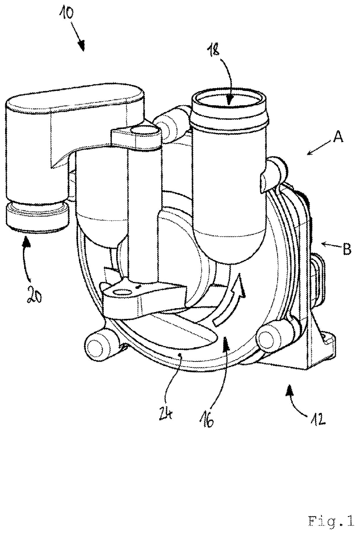
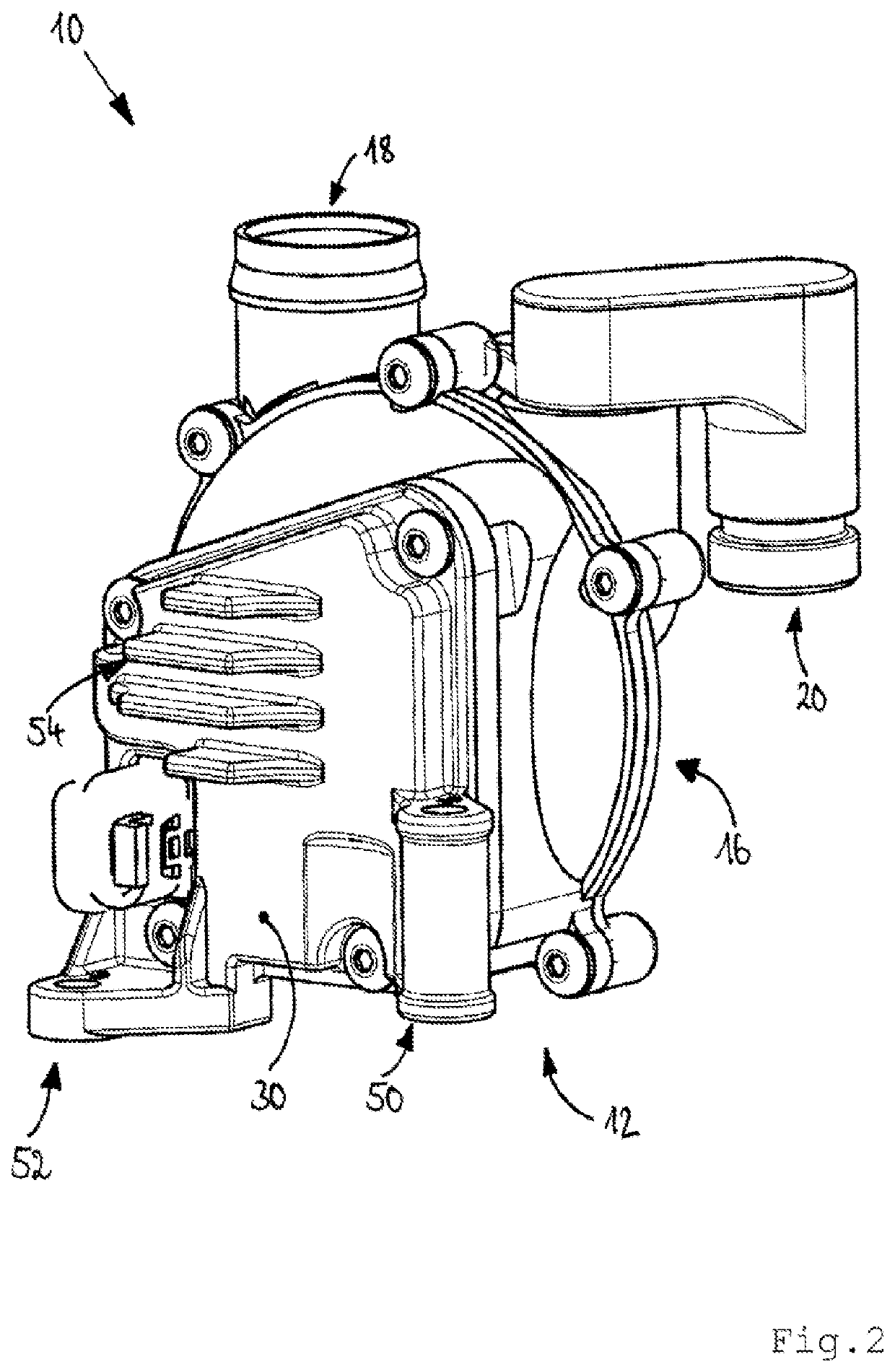
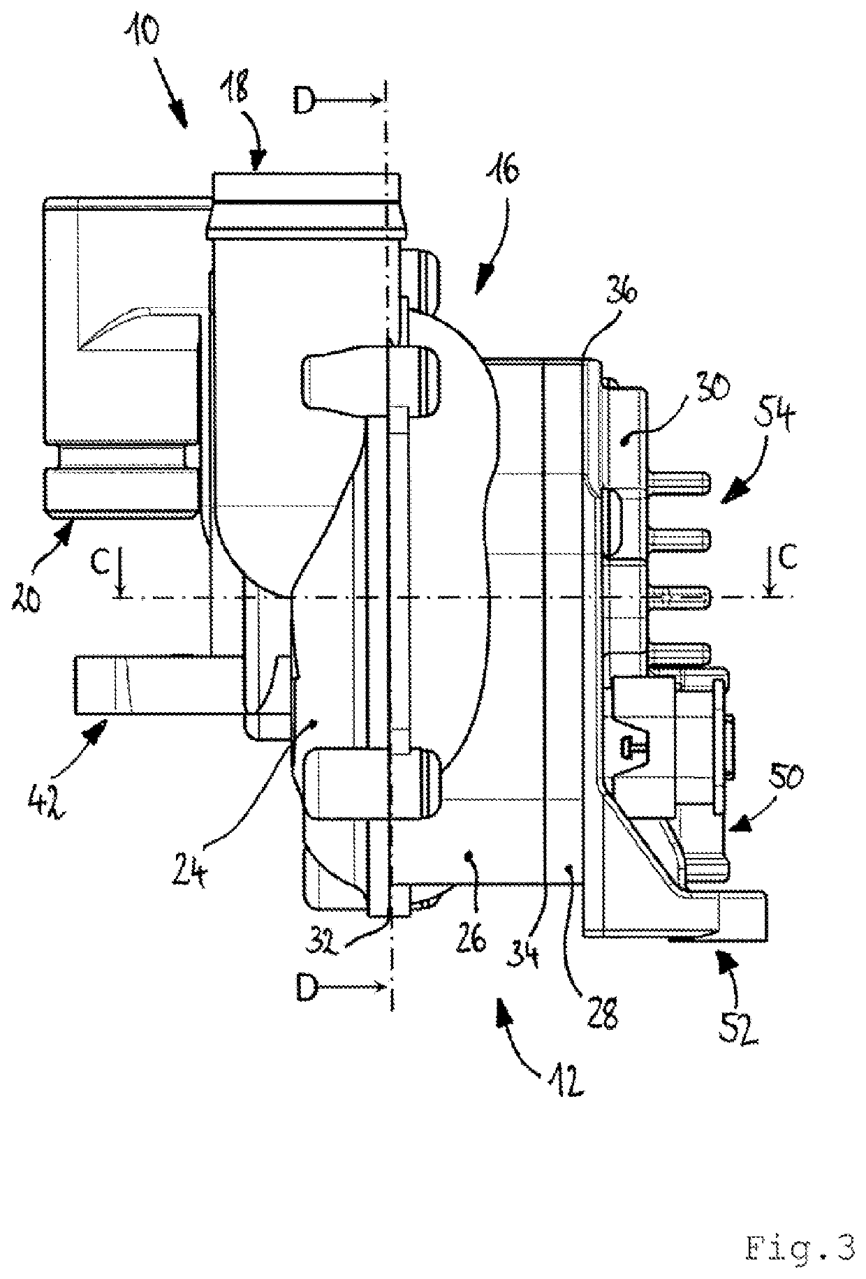
[0035]FIG. 1 shows a suction device for crankcase ventilation of an internal combustion engine and is designated overall by reference sign 10. The suction device 10 has a housing 12, a controllable electric motor 14 (see FIG. 4) and a compressor 16 driven by the electric motor 14 for conveying crankcase gas (see FIG. 1). The electric motor 14 is arranged in the housing 12.

[0036]The compressor 16 has connection points 18, 20 for connection to a crankcase ventilation line 102 (see FIG. 6). Thus, by controlling the electric motor 14, in particular by controlling its engine speed, the crankcase pressure of the internal combustion engine may be controlled.

[0037]The connection point 18 is an output from the compressor 16 (see FIG. 1). The connection point 20 serves as an input into the compressor 16. A section of a crankcase ventilation line may be connected at the connection point 20, which connects the crankcase of the internal combustion engine to the connection point 20 of the compres...


PUM


Abstract

The invention enables an adequate crankcase negative pressure in an internal combustion engine, in all operating ranges to the extent possible and using a suction device for the crankcase ventilation of an internal combustion engine, which suction device is equipped with a housing, a controllable electric motor and a compressor for conveying crankcase gas, which compressor is driven by the electric motor, the compressor having connection points for a crankcase ventilation line, such that the crankcase pressure of the internal combustion engine is controllable by controlling the electric motor.

Description

CROSS REFERENCE TO RELATED APPLICATIONS[0001]This is a National stage application, filed under 37 U.S.C. 371, of the International application No. PCT / EP2019 / 050207, filed on Jan. 7, 2019, which claims priority to German Patent Application No. DE 10 2018 106 881.6, filed Mar. 22, 2018, the entire contents of which is incorporated herein by reference.BACKGROUND[0002]The invention relates to a suction device for the crankcase ventilation of an internal combustion engine. The invention further relates to a crankcase ventilation for discharging crankcase gas from an internal combustion engine. The invention also relates to an internal combustion engine.[0003]The classic crankcase ventilation, in which negative pressure is used to extract crankcase gas from the intake tract of the internal combustion engine, is known from the prior art for the discharge of crankcase gas from the crankcase of an internal combustion engine. A crankcase ventilation line provides a flow connection between th...

Claims


Application Information

Patent Timeline
Patent Type & Authority Patents(United States)
IPC IPC(8): F01M13/04F01M13/02F01M13/00F04D25/04F04D29/28
CPCF01M13/04F01M13/022F01M2013/0005F01M2013/026F01M2013/027F04D25/045F04D29/284F01M13/02
Inventor STRÖSE, JÖRGSCHEIBE, CHRISTIANKÖHNLEIN, TOBIAS
Owner JOMA POLYTEC
Why Eureka
Try Eureka