

Impact tool
a technology of impact tool and impact plate, which is applied in the field of impact tool, can solve problems such as abnormal noise, and achieve the effect of abnormal nois
- Summary
- Abstract
- Description
- Claims
- Application Information
AI Technical Summary
Benefits of technology
Problems solved by technology
Method used
Image

Examples
first embodiment
Overview of Impact Tool
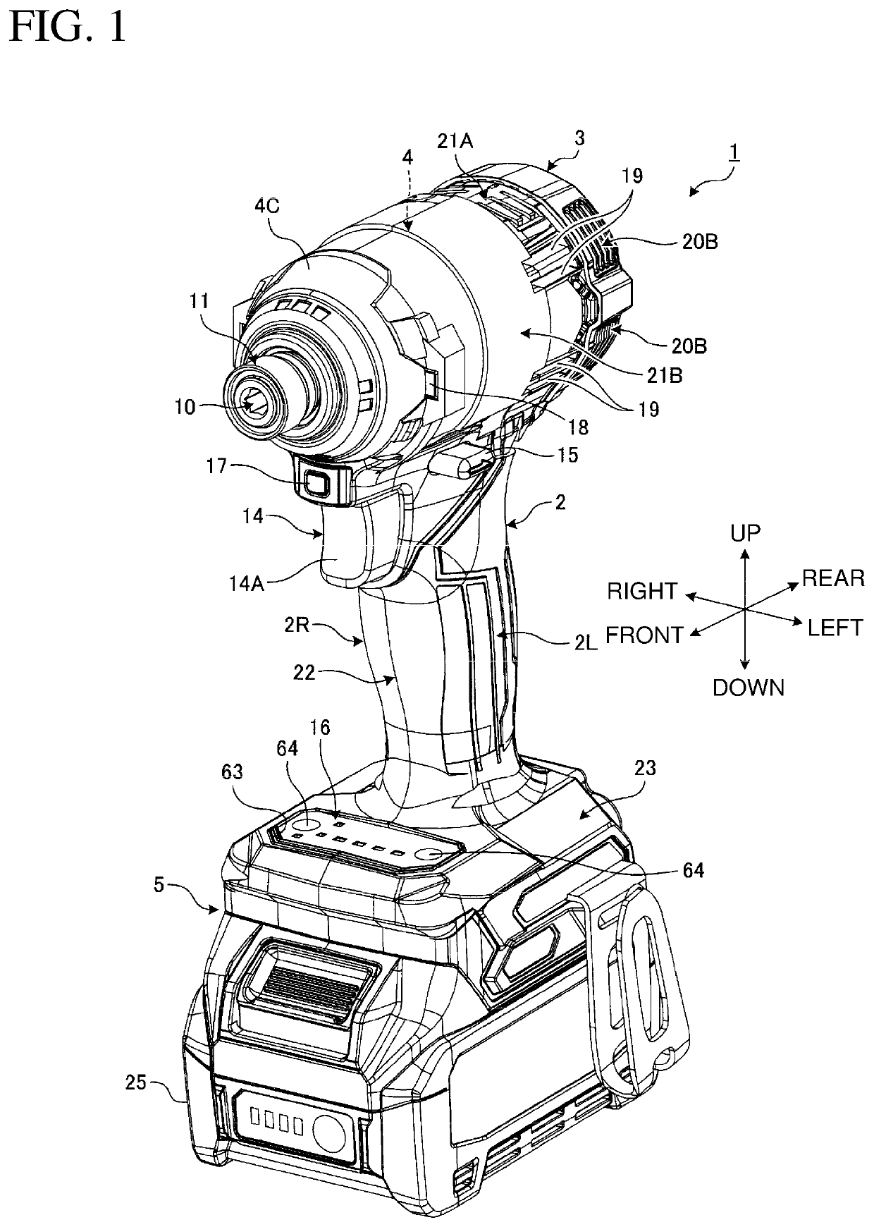
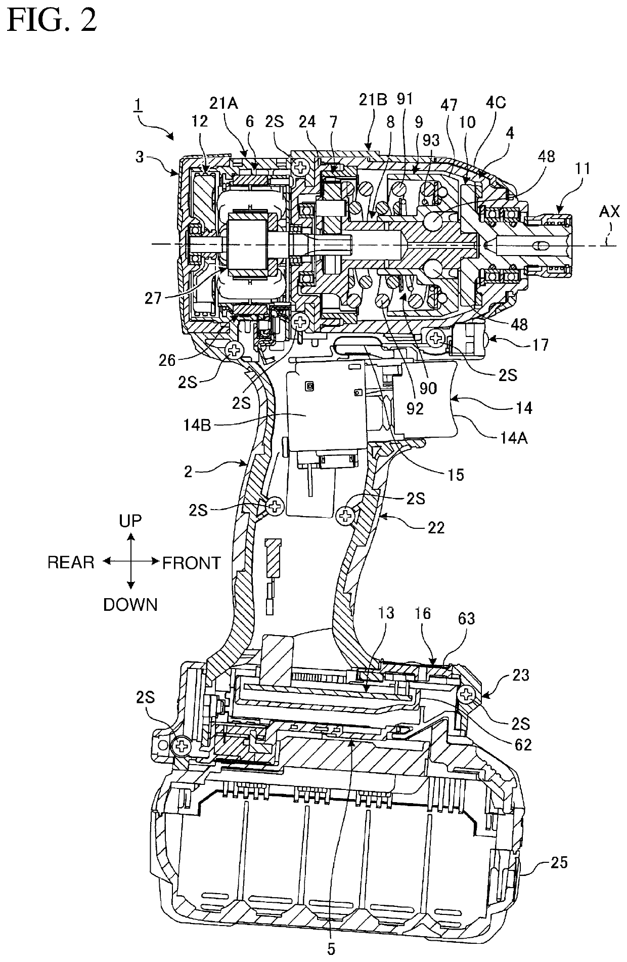
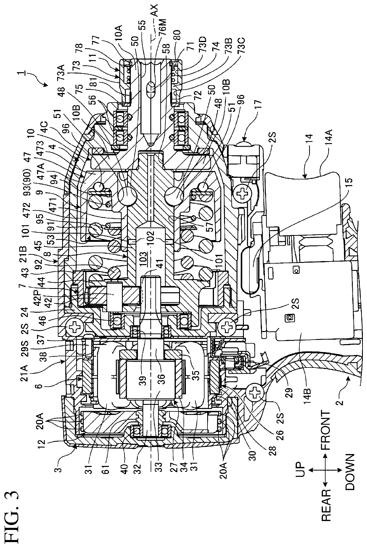
[0031]FIG. 1 is a perspective view of the impact tool 1 according to the present embodiment. FIG. 2 is a longitudinal sectional view of the impact tool 1 according to the present embodiment. FIG. 3 is a partially enlarged longitudinal sectional view of the impact tool 1 according to the present embodiment. FIG. 4 is a partially enlarged transverse sectional view of the impact tool 1 according to the present embodiment. The impact tool 1 is an impact driver including an impact mechanism 9 and an anvil 10.
[0032]As shown in FIGS. 1 to 4, the impact tool 1 includes a housing 2, a rear case 3, a hammer case 4, a battery mount 5, the motor 6, a reduction mechanism 7, the spindle 8, the impact mechanism 9, the anvil 10, a tool holder 11, a fan 12, a controller 13, a trigger switch 14, a forward-reverse switch lever 15, an operation panel 16, a mode switch 17, and lamps 18.
[0033]The housing 2 is formed from a synthetic resin. The housing 2 in the present embodiment is...
second embodiment
[0183]A second embodiment will now be described. The same or corresponding components as those in the above embodiment are given the same reference numerals herein, and will be described briefly or will not be described.
[0184]FIG. 9 is a longitudinal sectional view of an impact mechanism 9 according to the present embodiment. A movement restrictor 90 restricts movement of the rear end of the second spring 92 relative to a spindle 8. In other words, the movement restrictor 90 restricts free movement of the rear end of the second spring 92 relative to the spindle 8. As shown in FIG. 9, the movement restrictor 90 includes a fixing portion 200 for fastening the rear end of the second spring 92 to at least a part of the spindle 8. The fixing portion 200 according to the present embodiment is located on a flange 44 on the spindle 8. The fixing portion 200 includes a groove 201 on the front surface of the flange 44. The rear end of the second spring 92 is press-fitted in the groove 201 on ...
third embodiment
[0192]A third embodiment will now be described. The same or corresponding components as those in the above embodiment are given the same reference numerals herein, and will be described briefly or will not be described.
[0193]FIG. 10 is a longitudinal sectional view of an impact mechanism 9 according to the present embodiment. A movement restrictor 90 according to the present embodiment restricts movement of the front end of the second spring 92 relative to a hammer 47. In other words, the movement restrictor 90 restricts free movement of the front end of the second spring 92 relative to the hammer 47. As shown in FIG. 10, the movement restrictor 90 includes a fixing portion 300 for fastening the front end of the second spring 92 to at least a part of the hammer 47. The fixing portion 300 according to the present embodiment is located on an inner cylinder 471 in the hammer 47. The fixing portion 300 includes a groove 301 on the inner cylinder 471. The front end of the second spring 9...
PUM
 Abstract
Description
Claims
Application Information