
Monitoring device

a monitoring device and a technology for monitoring devices, applied in the field of monitoring devices, can solve the problems of difficult to obtain a filtering function that only detects the correct signals, the measurement and display of a set dose is accurate, and the manufacturing cost of the medical device becomes rather high

Active Publication Date: 2022-09-13
SHL MEDICAL AG
View PDF14 Cites 0 Cited by
  • Summary
  • Abstract
  • Description
  • Claims
  • Application Information

AI Technical Summary

Benefits of technology

This patent aims to improve monitoring devices by using both an optical sensor and a vibration sensor to accurately measure the movement of a medicament delivery device. This compensates for any deviations or tolerance flaws in the device, resulting in a more accurate measurement. Overall, this monitoring device can display a set dose with greater accuracy.

Problems solved by technology

One is that the medicament delivery device becomes rather complicated and expensive to manufacture.
This is especially a problem if the medicament delivery device is a so called disposable device that is to be discarded after use.
Another drawback is that it is not a simple task to modify a medicament delivery device that already is on the market by integrating monitoring functionality, because such modifications require new approvals from national health authorities before they can be marketed.
There are some drawbacks with the design of U.S. Pat. No. 9,101,723.
Even so, it is often difficult to obtain such a filtering function that only detects the correct signals.
Further, correct signals may is some instances be “hidden” by other signals that may occur simultaneously, whereby the filtering function may miss the correct signal.

Method used


Image

  • Monitoring device
  • Monitoring device
  • Monitoring device

Examples


Embodiment Construction

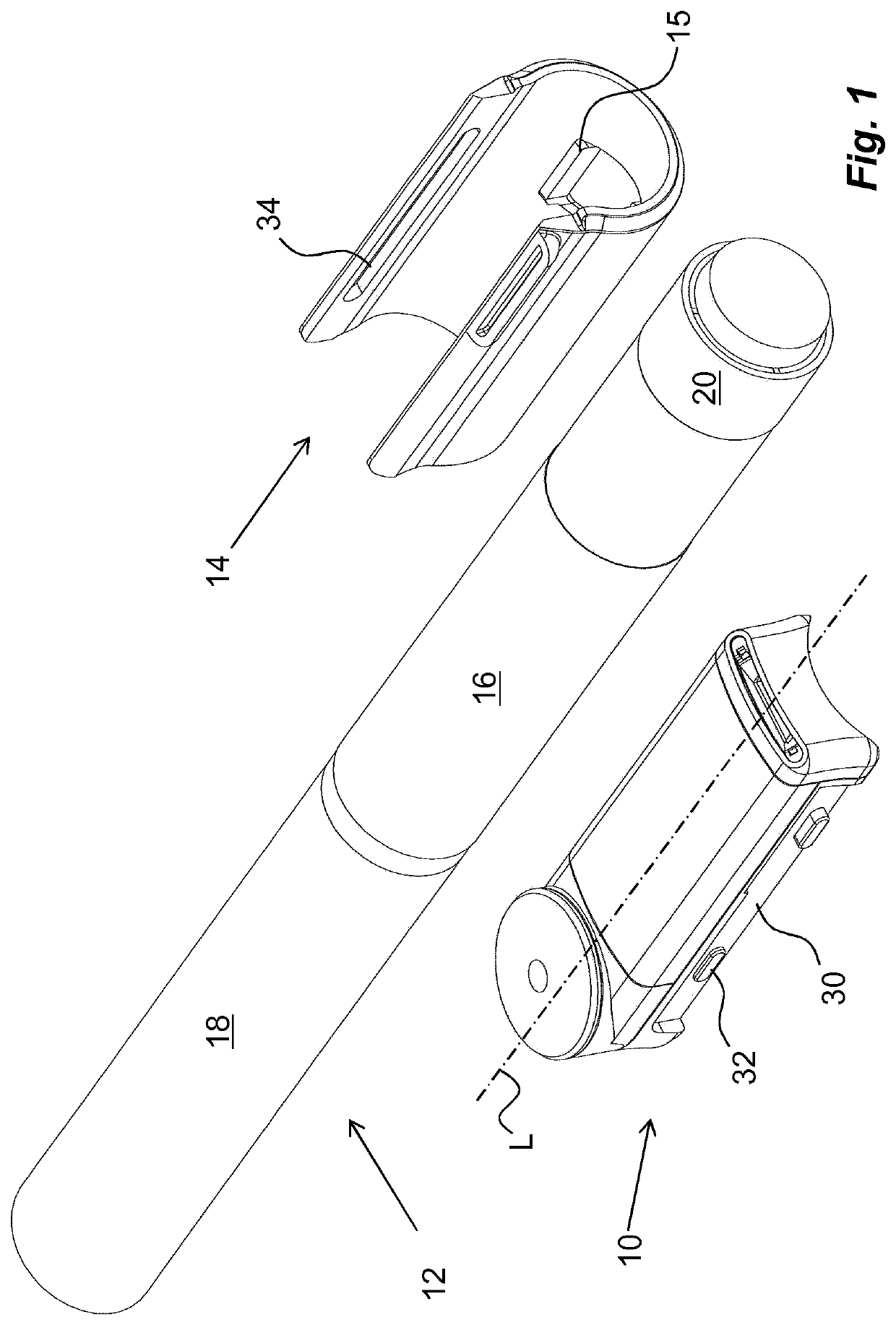
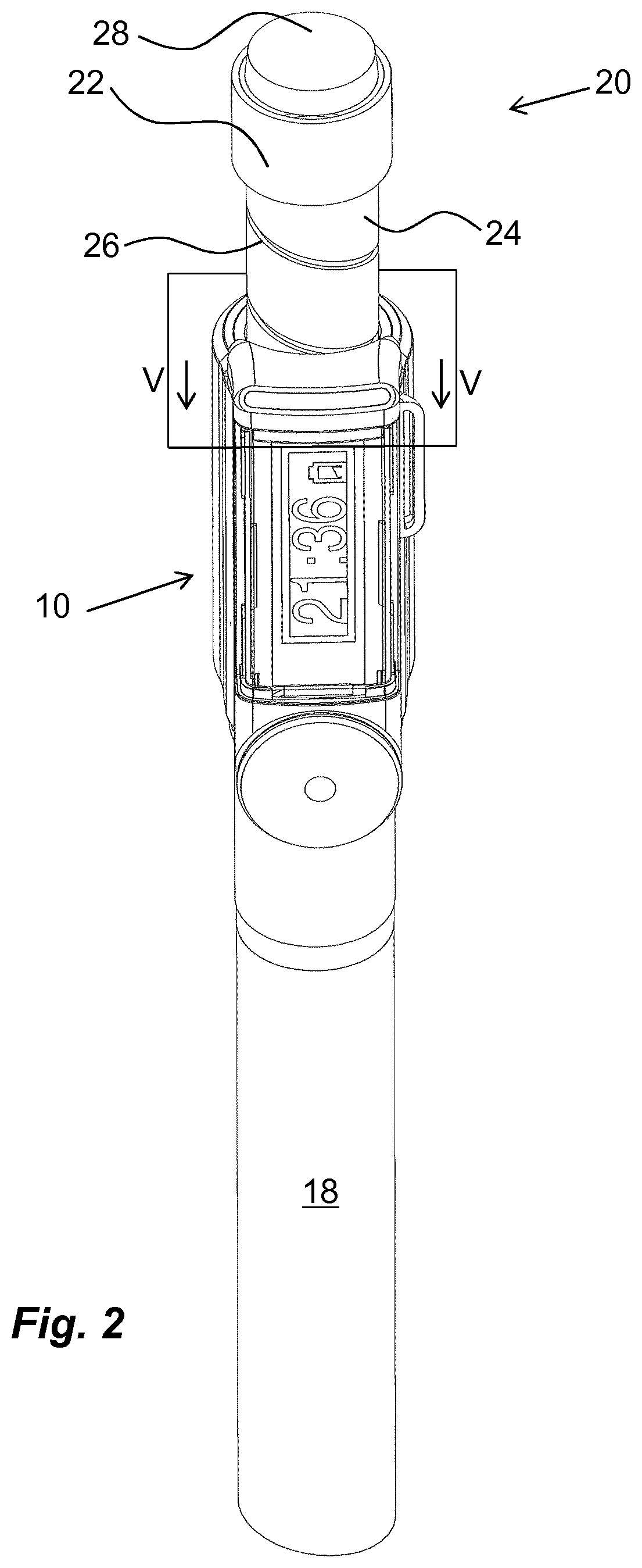
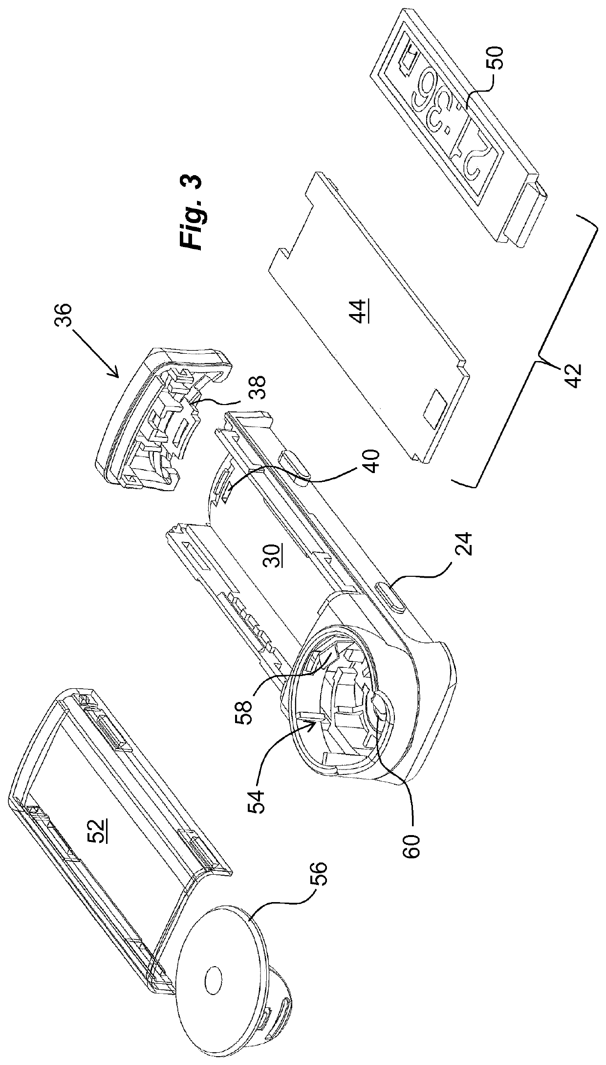
[0027]The present invention relates to a smart monitoring device or unit 10 for monitoring the use of medicament delivery devices 12 such as insulin pens as seen in FIG. 1 even though it should be understood that a number of different medicaments may be delivered by the medicament delivery device. The monitoring unit 10 may be connected to the medicament delivery device 12 by suitable connecting elements. FIG. 1 shows one example of a connecting element in the form of an annular sleeve 14 that is designed to be removably mounted on the outside of the medicament delivery device in a secure way. In this regard, the sleeve 14 is preferably adapted to the outer shape and dimensions of the medicament delivery device it is intended to be connected to as well as mechanical fixation elements 15 such as protrusions and / or ledges that are to cooperate with corresponding support surfaces on the medicament delivery device such as side surfaces around an opening or a window for e.g. a dose count...


PUM


Abstract

The present invention relates to a monitoring device (10) arranged to be operably connected to a medicament delivery device (12), said medicament delivery device (12) comprising a manually operated movable dose activation element (20), said monitoring device (10) comprising an electronic circuit (42), said electronic circuit (42) comprising an optical sensor (68), wherein said optical sensor (68) is positioned in relation to said dose activation element (20) so as to detect a manual operation of said dose activation element (20) from an initial position; said electronics circuit further comprising a vibration sensor (70), wherein said vibration sensor (70) is positioned in relation to said medicament delivery device so as to detect specific vibration spectra produced by the medicament delivery device when said dose activating element (20) is operated, wherein said electronic circuit (42) comprises computing elements capable of correlating the information from the optical sensor (68) with the information from the vibration sensor (70) when said dose activation element (20) is operated in order to register when a correct dose has been set.

Description

CROSS REFERENCE TO RELATED APPLICATIONS[0001]The present application is a U.S. National Phase Application pursuant to 35 U.S.C. § 371 of International Application No. PCT / EP2018 / 054844 filed Feb. 27, 2018, which claims priority to European Patent Application No. 17158507.8 filed Feb. 28, 2017. The entire disclosure contents of these applications are hereby incorporated by reference into the present application.BACKGROUND OF INVENTION[0002]There is an ever increased demand for monitoring the handling of medicament delivery devices and in particular medicament delivery devices for self-administration. One important reason for monitoring the handling is to provide a user with information and alerts as to when the next dose delivery is scheduled, based on previous dose deliveries and based on prescribed medication schedules.[0003]Some medicament delivery devices are provided with monitoring units integrated into the medicament delivery device. This has a number of drawbacks. One is that...

Claims


Application Information

Patent Timeline
Patent Type & Authority Patents(United States)
IPC IPC(8): A61M5/31A61M5/315
CPCA61M5/31568A61M2005/3126A61M2205/3306A61M2205/3327A61M2205/3368A61M2205/3375A61M2205/3569A61M2205/3584A61M2205/502A61M2205/505A61M2205/581A61M5/24A61M5/31533A61M5/31556A61M5/31573A61M2005/3142A61M2205/33A61M2205/50
Inventor CIRILLO, WILLIAM
Owner SHL MEDICAL AG
Learn More