Catheter, a coupling component for coupling the catheter to tubes, an apparatus including the rectal catheter, and a method of manufacturing the catheter

a technology of coupling components and catheters, applied in the field of catheters, can solve the problems of inconvenient rectum recurrence, unwelcoming patients, demeaning patients, etc., and achieve the effect of reducing increasing the pain and discomfort of patients

Active Publication Date: 2022-09-20
MBH INT AS
View PDF18 Cites 0 Cited by
  • Summary
  • Abstract
  • Description
  • Claims
  • Application Information

AI Technical Summary

Benefits of technology

[0023]It is yet an aspect of the present invention to provide a rectal catheter of the kind mentioned in the opening paragraph that makes it possible to perform transanal irrigation without soiling the user and the surroundings.
[0085]Thus using multi-component injection molding facilitates combining a hard thermoplastic component with an elastic, and even a super-elastic, plastic component, e.g. made of silicone.

Problems solved by technology

Even though the balloon in these known systems will assist the patient by helping to keep the tubular part of an irrigation rectal catheter in the correct place inside the rectum during the irrigation, these systems have the major drawback that if the balloon is inflated too much it is harmful to the patient, and if the balloon is inflated too little it cannot safely keep the tube in place during use due to the air-filled balloon reacting to the body movements, e.g. peristaltic reflexes, resulting in that the tube inconveniently may fall out of rectum as well as leakage of injected liquid around the inflated balloon can occur.
This is not only unwelcoming for the patient but also very demeaning, as the surroundings inevitability will be contaminated with irrigation liquid and bodily excretions.
If the air at this stage was delivered to the rectum and / or bowel this would result in an additional distending or dilation resulting in additional pain and discomfort for the patient.
Fluids having higher density, such as e.g. water or saline, however cannot flow easily through these conventional tiny air holes below the balloon.
The user needs to apply a very high inflation pressure at the risk of causing unintentional detachment of tubes or hoses and rectal catheter because the liquid will find another way out of the system, as well as it will take considerable time to distend the balloon of the above known irrigation systems with liquid delivered through tiny holes.
The means for connecting this known catheter does however not conform to anatomical shape and may be difficult to operate due to being hard to reach.

Method used


Image

  • Catheter, a coupling component for coupling the catheter to tubes, an apparatus including the rectal catheter, and a method of manufacturing the catheter
  • Catheter, a coupling component for coupling the catheter to tubes, an apparatus including the rectal catheter, and a method of manufacturing the catheter
  • Catheter, a coupling component for coupling the catheter to tubes, an apparatus including the rectal catheter, and a method of manufacturing the catheter

Examples


first embodiment

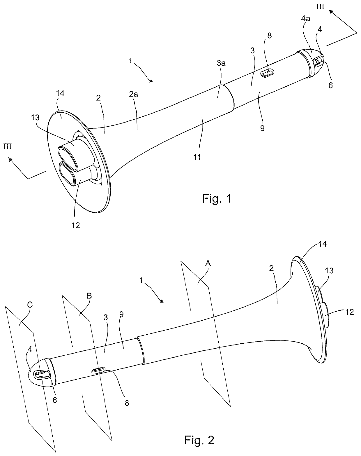
[0118]a rectal catheter 1 shown in perspective in FIGS. 1-6 is shown without expandable fixation member. It should however be understood that the rectal catheter 1 includes an expandable fixation member, which in the following detailed description is an elastic balloon to be infused with a liquid.

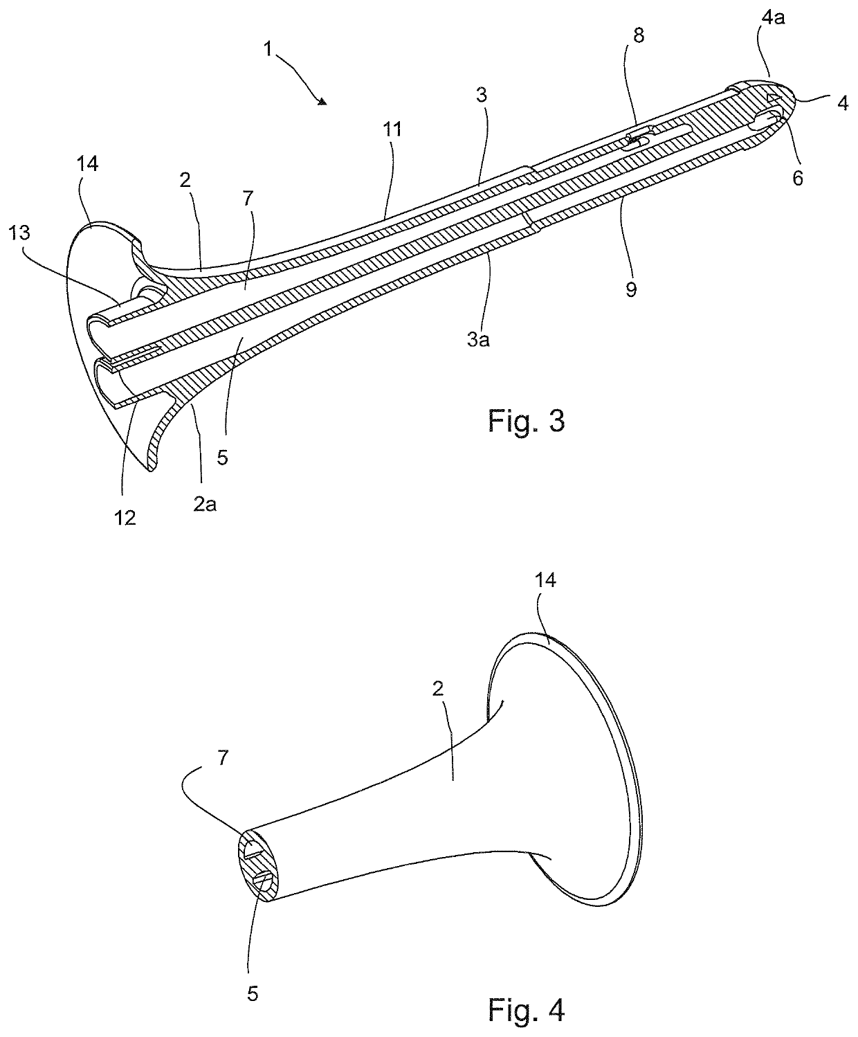
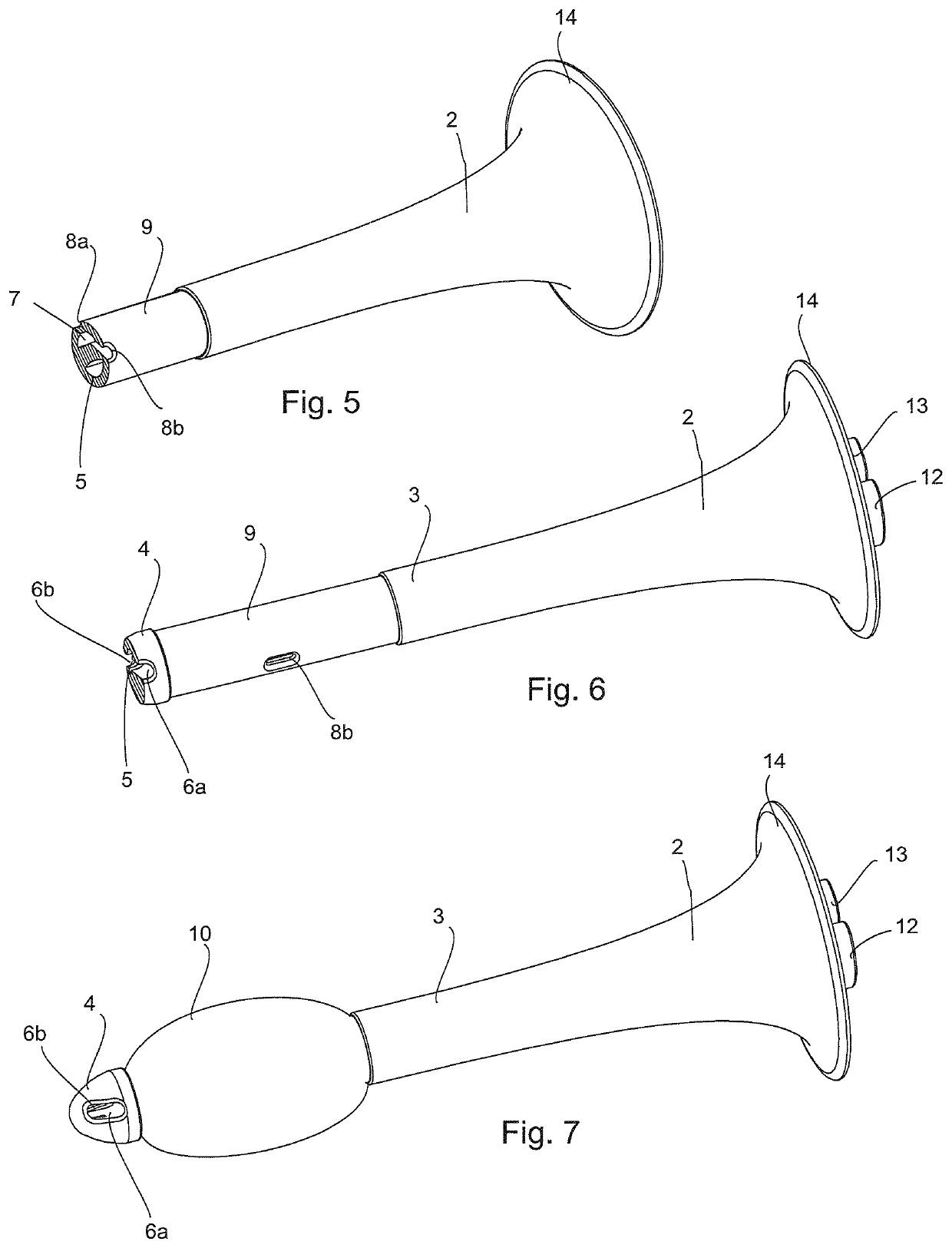
[0119]The rectal catheter has a funnel-shaped part 2 that tapers into an elongated catheter part 3. The elongated catheter part 3 has a free end 4 opposite the funnel-shaped part 2, which free end serves for expelling liquid into a body cavity, such as rectum and up the intestinal duct.

[0120]As seen more clearly in the longitudinal sectional view of FIG. 3 a liquid flow channel 5 extends lengthwise the funnel-shaped part 2 into the elongated catheter part 3 and ends in an injection opening 6 at the free end 4 of said elongated catheter part 3 to expel injection liquid flowing in a liquid flow channel 5 from an injection liquid reservoir (not shown). A fluid flow channel 7 extends parallel t...

second embodiment

[0138]The flow converter member 31 may have an enlargement 32 for improving the grasping facility of a coupling component 24.

[0139]Also the first embodiment of a coupling component 15 can have elongate coupling pieces 28,30 instead of just coupling openings 19,21 in order to extend the third flow channel 18 and the fourth flow channel 20. The elongate coupling pieces 28,30 may be rigid or elastic as required for a given coupling task and coupling environment.

[0140]Furthermore, the coupling pieces 28,30 may be longer than shown, e.g. extend into flexible tubes that serve for connecting to a valve means.

[0141]Depending on the actual irrigation environment, the convenience around the user, the users preferred position during irrigation, and the further equipment, the user may choose to use any of the coupling components 15,24, or none at all together with the first embodiment of a catheter 1.

[0142]FIG. 14 shows, in a partly exploded view, a rectal injection apparatus 33 using the recta...

embodiment 41

[0146]The second catheter embodiment 41 has a funnel-shaped part 42 that tapers into an elongated catheter part 43. The elongated catheter part 43 has a free end 44 opposite the funnel-shaped part 42, which free end 44 serves for expelling liquid into a body cavity.

[0147]As seen more clearly in the longitudinal sectional view of FIG. 17 a liquid flow channel 45 extends lengthwise the funnel-shaped part 42 into the elongated catheter part 43 and ends in two opposite injection openings 46 at the free end 44 of said elongated catheter part 43 to expel injection liquid flowing in the liquid flow channel 45 from an injection liquid reservoir, e.g. the drip bag 38 seen in FIG. 14. A fluid flow channel 47 that surrounds the liquid flow channel 45 ends in an elongate delivery opening 48 at an elongate fixation section 49 of the elongated catheter part 43 distal to the free end 44. The elongate fixation section 49 is configured for attaching and fluid-tight securing the fixation member (not ...


PUM

PropertyMeasurementUnit
diameteraaaaaaaaaa
sizeaaaaaaaaaa
anglesaaaaaaaaaa

Abstract

A catheter for use with an injection apparatus, preferably for rectal irrigation. The catheter has a main body with a funnel-shaped part delimited by an annular funnel wall which tapers into an elongate tubular catheter part delimited by an annular catheter wall. The main body accommodates at least a liquid flow channel and a fluid flow channel and the liquid flow channel is adapted to expel a liquid via at least one injection opening in a free end of the elongate tubular catheter part opposite the funnel-shaped part. An expandable balloon surrounds an elongate fixation section of the elongate tubular catheter part a distance from its free end, and the fluid flow channel is adapted to, via at least one delivery opening provided in the annular catheter wall of the elongate fixation section of the elongate tubular catheter part, deliver a fluid to the expandable balloon.

Description

CROSS-REFERENCE TO RELATED APPLICATIONS[0001]This application is a continuation of International patent application PCT / DK2017 / 050338 filed Oct. 12, 2017 claiming priority of Danish application PA 2016 70486 filed Oct. 28, 2016.BACKGROUND[0002]The present invention relates to a catheter adapted for injection of a liquid into a body cavity, said catheter being coupled to a coupling component adapted to couple to tubes for establishing fluid communication to an injection liquid reservoir, said catheter has[0003]a main body comprising a funnel-shaped part delimited by an annular funnel wall and an elongate tubular catheter part delimited by an annular catheter wall, which funnel-shaped part has a flared part that, via a smooth transition, tapers into a tapering part, which extend into the elongate tubular catheter part,[0004]the main body accommodates a liquid flow channel, which is adapted to expel a liquid via at least one injection opening in a free end of the elongate tubular cathe...

Claims


Application Information

Patent Timeline
Patent Type & Authority Patents(United States)
IPC IPC(8): A61M3/02A61M25/00A61M25/10A61M39/10A61M25/04A61B17/00B29C45/16
CPCA61M3/0295A61M3/0279A61M25/0009A61M25/10181A61M39/105A61B2017/00526A61M3/022A61M3/0208A61M3/0262A61M25/04A61M2025/0073A61M2039/1016A61M2207/00A61M2210/1064A61M2210/1067B29C45/1676
Inventor HOUGAARD, OLEDUE, CATHRINE ØRSNESBJERREGAARD, HENRIK BORK
Owner MBH INT AS
Why Eureka
Try Eureka