
Touch panel sensor with optimal electrode separation for improved performance

a technology of electrode separation and touch panel, applied in the direction of instruments, computing, electric digital data processing, etc., can solve the problems of display emission interference, incorrect detection, damage to the touch panel device, etc., and achieve the effect of increasing electrode separation, and significantly reducing mutual capacitan

Active Publication Date: 2022-09-20
SHARP DISPLAY TECH CORP
View PDF5 Cites 0 Cited by
  • Summary
  • Abstract
  • Description
  • Claims
  • Application Information

AI Technical Summary

Benefits of technology

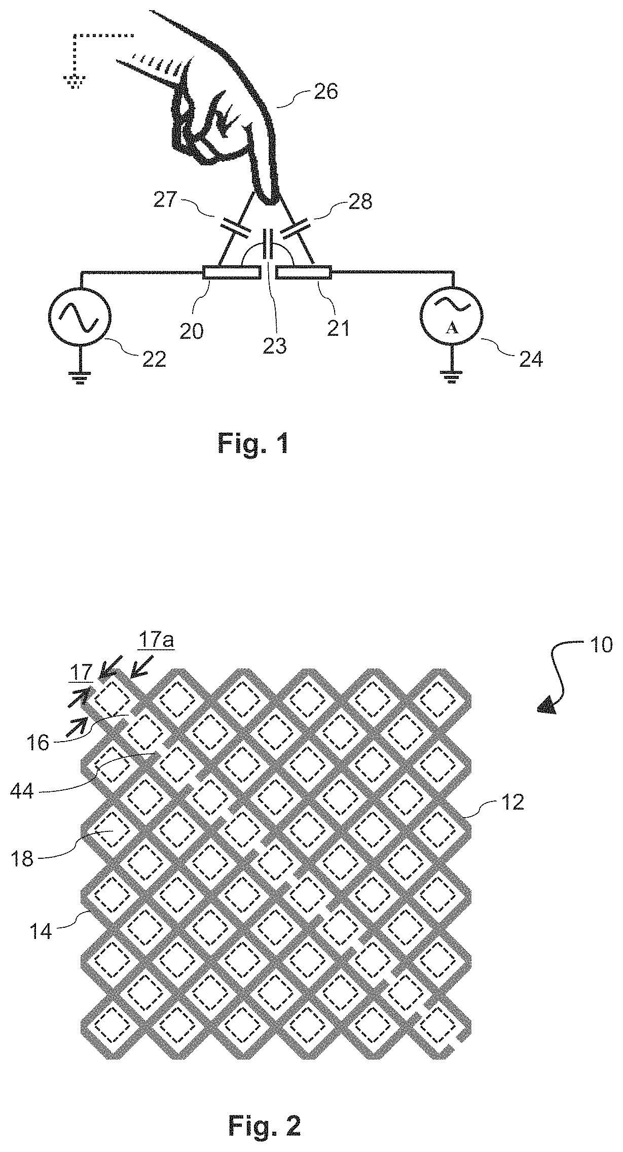
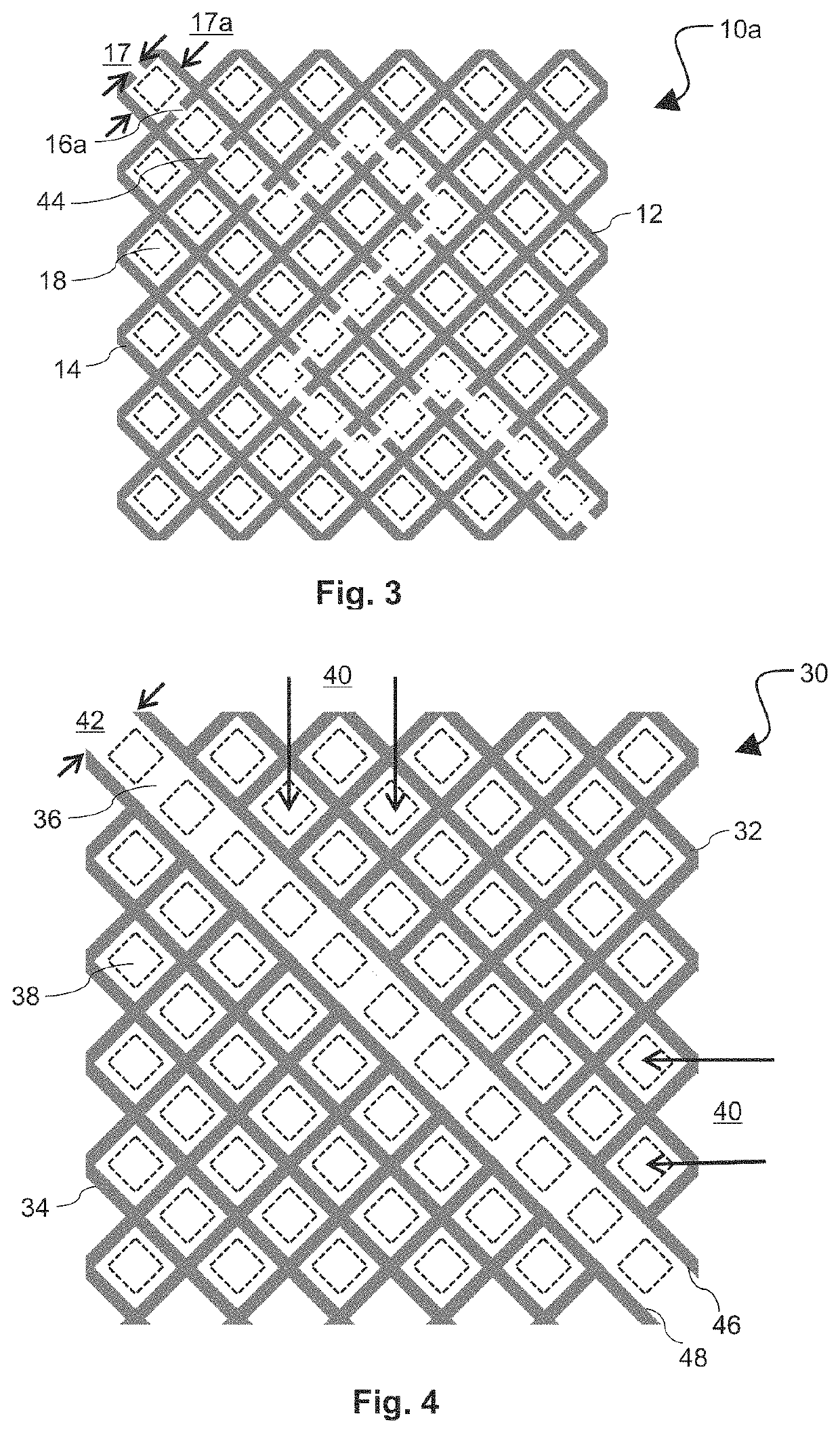
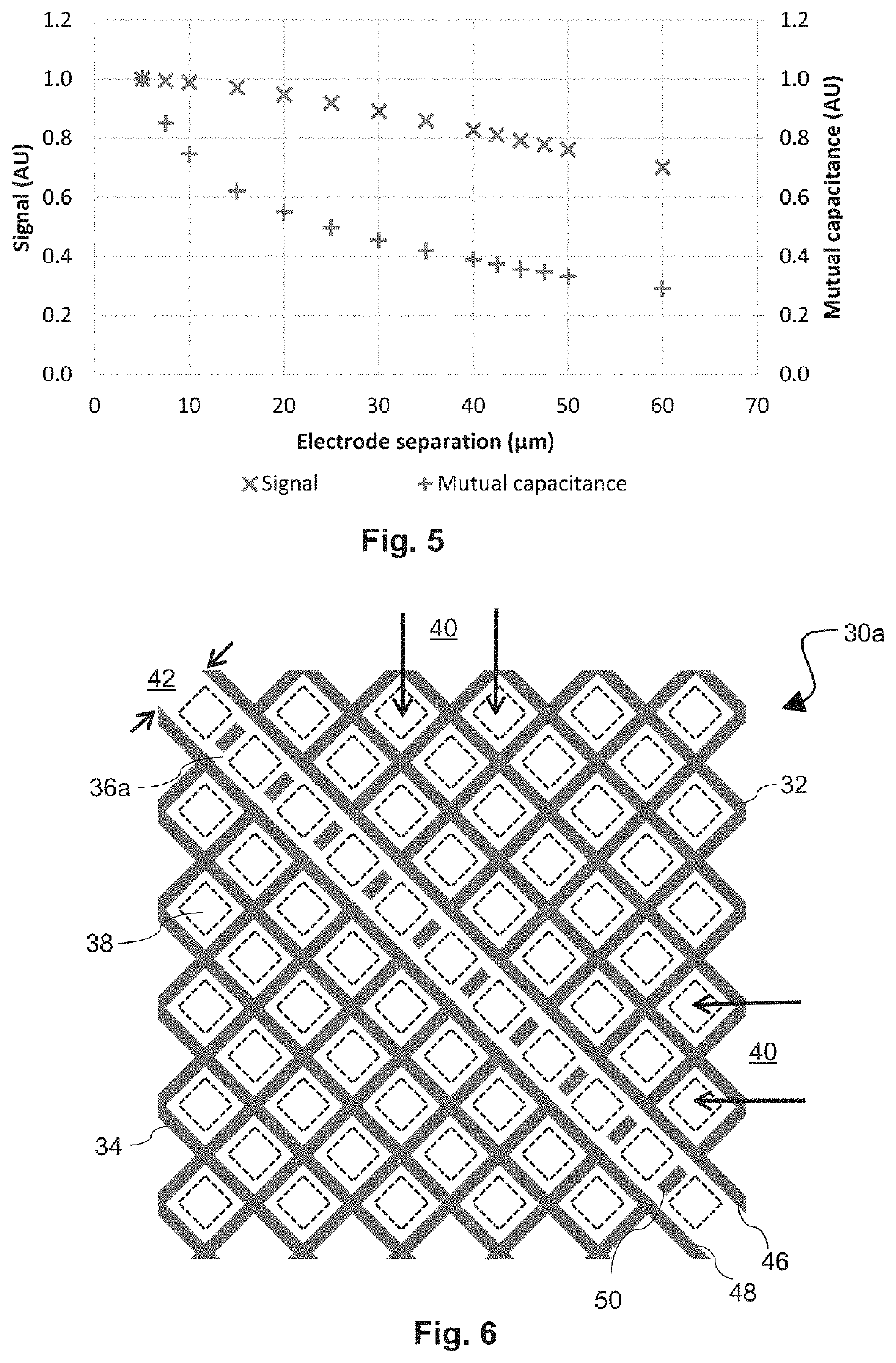
The present invention is about an improved design of a touch panel sensor that reduces mutual capacitance and maintains a high touch signal magnitude while remaining invisible to the viewer. The touch electrode configuration achieves a significant reduction in mutual capacitance as electrode separation is increased. This configuration allows for optimal electrode separation distance that accounts for competing considerations of lower mutual capacitance and sufficient output signal magnitude. Overall, the technical effect of this invention is an improved touch panel sensor with reduced mutual capacitance and enhanced output zone while maintaining sufficient output signal magnitude and invisibility to the viewer.

Problems solved by technology

For more effective touch panel performance, however, the touch panel row and column electrodes may be formed of a metal which is highly conductive but not transparent, and thus would interfere with display emission if the touch panel sensor electrodes were overlaid directly over the display pixels.
If the electrode separation distance is too small, there is a risk of electrical contact or shorting between row and column electrodes, which causes incorrect detection of objects and can also cause damage to the touch panel device.
Despite such higher magnitude signal output, however, the use of high mutual capacitances has drawbacks.
Higher capacitive loads can be detrimental to touch panel driver performance in that higher capacitive loads affect the speed at which electrical signals can be applied to the electrodes, with signal speed decreasing as the mutual capacitance increases.
The interlocking metal mesh electrodes have fine features formed on thin conductive layers, and thus minimal electrode separation distance can result in defects in the formation of the electrode layer which can result in low manufacturing yield.
For example, shorting defects of unwanted electrical contact between the two electrodes can occur across the insulating region.
There are limits, however, on the amount by which the electrode separation distance can be increased.
With increasing electrode separation distance, the insulating region eventually will become visible to the viewer as an interruption of the display emission, and the magnitude of the output signal also degrades and ultimately becomes insufficient.
Prior attempts at optimization of the touch panel electrode configuration of touch panel sensors have proven deficient to balance these considerations.

Method used


Image

  • Touch panel sensor with optimal electrode separation for improved performance
  • Touch panel sensor with optimal electrode separation for improved performance
  • Touch panel sensor with optimal electrode separation for improved performance

Examples


Embodiment Construction

[0028]Embodiments of the present application will now be described with reference to the drawings, wherein like reference numerals are used to refer to like elements throughout. It will be understood that the figures are not necessarily to scale.

[0029]The present application describes an improved design of a touch panel sensor having a touch electrode configuration that reduces mutual capacitance significantly, without a commensurate degrading of the output signal magnitude and while remaining invisible to a viewer. As referenced above, in conventional configurations it is expected by one of ordinary skill in the art that the magnitude of the touch signal would decrease proportionally to the decrease in mutual capacitance when the electrode separation distance is increased. The inventors of the current application, however, have designed a touch electrode configuration whereby as the electrode separation distance is increased within an optimal range, a disproportionately small reduc...


PUM

PropertyMeasurementUnit
separation distanceaaaaaaaaaa

Abstract

A touch panel display includes a display panel having a plurality of pixel regions that emit light, and a touch sensor having an electrode configuration that overlays the display panel. The electrode configuration includes a first electrode and a second electrode that are separated by an insulating region. The electrode separation distance between the first and second electrodes is in a range whereby (1) with increasing electrode separation distance a first rate of proportional decrease in mutual capacitance between the first and second electrodes is greater than a second rate of proportional decrease in signal magnitude of an output signal, and (2) a ratio (R) of the first rate to the second rate satisfies the relationship 1.0<R<2.5. With such parameters, the electrode separation distance may be from 30 μm to 50 μm, and / or from 0.5 to 0.75 times a pixel pitch of the pixel regions.

Description

TECHNICAL FIELD[0001]The present application relates to touch panel devices, and capacitive type touch panel devices in particular including high performance mutual capacitance touch panels configured with rows and columns of electrodes for detecting conductive and non-conductive input objects.BACKGROUND ART[0002]Touch panels have become widely adopted as the input device for a range of electronic products such as smart-phones, tablet devices, and computers. Many high-end portable and handheld electronic devices now include touch panels. These are most often used as part of a touchscreen, i.e., a display panel and a touch panel that are aligned so that the touch zones of the touch panel correspond with display zones of the display panel. The most common user interface for electronic devices with touchscreens is an image on the display panel, the image having points that appear interactive. For example, the device may display a picture of a button, and the user can then interact with...

Claims


Application Information

Patent Timeline
Patent Type & Authority Patents(United States)
IPC IPC(8): G06F3/044G06F3/041
CPCG06F3/0446G06F3/0412G06F2203/04112G06F3/0448
Inventor YUDIN, ALEXKAY, ANDREWMIYAZAKI, SHINICHI
Owner SHARP DISPLAY TECH CORP
Learn More