Antenna module

a technology of antenna module and antenna body, applied in the direction of loop antenna, transmission, radiating element structure, etc., to achieve the effect of minimizing the shadow, increasing the recognition area, and minimizing the shadow of the portable terminal

Active Publication Date: 2022-09-20
AMOTECH
View PDF32 Cites 0 Cited by
  • Summary
  • Abstract
  • Description
  • Claims
  • Application Information

AI Technical Summary

Benefits of technology

[0017]According to the present disclosure, the antenna module may connect the metal deco to the radiation pattern and use the metal deco as the auxiliary radiator, thereby minimizing the shadow of the portable terminal in the near field communication (NFC) band to increase the recognition area.
[0018]In addition, the antenna module may dispose the deco panel by overlapping the radiation pattern, and use the deco panel as the auxiliary radiator through the coupling with the radiation pattern, thereby minimizing the shadow of the portable terminal in the near field communication (NFC) band to increase the recognition area.

Problems solved by technology

However, the portable terminal mounted with a conventional NFC antenna module enables communication only in an area in which a radiation pattern is disposed, thereby causing shadow.
Since the portable terminal mounted with the conventional NFC antenna module has shadow, there is a problem in that the specific location of the portable terminal mounted with the conventional NFC antenna module is required to be close to a reader or a tag upon short-range communication.

Method used


Image

  • Antenna module
  • Antenna module
  • Antenna module

Examples


Embodiment Construction

[0029]Hereinafter, the most preferred exemplary embodiments of the present disclosure will be described with reference to the accompanying drawings in order to specifically describe the exemplary embodiments so that those skilled in the art to which the present disclosure pertains may easily implement the technical spirit of the present disclosure. First, in adding reference numerals to the components of each drawing, it should be noted that the same components have the same reference numerals as much as possible even if they are displayed in different drawings. In addition, in describing the present disclosure, when it is determined that the detailed description of the related well-known configuration or function may obscure the gist of the present disclosure, the detailed description thereof will be omitted.

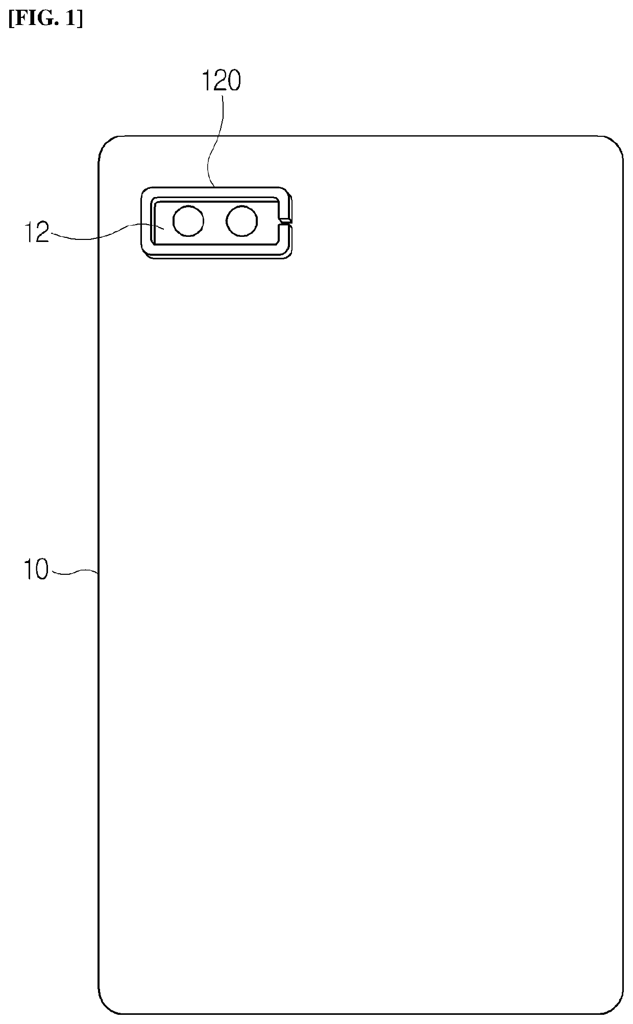
[0030]Referring to FIG. 1, an antenna module 100 according to a first exemplary embodiment of the present disclosure uses a metal deco 120 of a portable terminal 10 as an auxil...


PUM


Abstract

Provided is an antenna module for increasing a recognition area by using a metal deco or a deco panel of a portable terminal as an auxiliary radiator of a radiation pattern for near field communication. The provided antenna module includes: a metal deco disposed on a rear side of a portable terminal; and a radiation pattern connected to the metal deco, in which the metal deco is spaced at both ends by means of a slit, and one end is configured to be directly connected with one end of a radiation pattern so as to act as an auxiliary radiator of the radiation pattern.

Description

TECHNICAL FIELD[0001]The present disclosure relates to an antenna module, and more specifically, to an antenna module mounted on a portable terminal to perform near field communication.BACKGROUND ART[0002]With the development of technology, portable terminals such as a portable phone, a PDA, a PMP, a navigation terminal, and a laptop additionally provide a function of short-range communication between a DMB, a wireless Internet, and a device in addition to basic functions such as call, video / music play, navigation, and the like. Therefore, the portable terminal has a plurality of antenna for wireless communication such as a wireless Internet or a Bluetooth.[0003]In addition, in recent years, there is a trend of applying functions such as information exchange between terminals, payment, ticket reservation, and searching to the portable terminal using short-range communication (i.e., NFC). To this end, the portable terminal is mounted with an antenna module (i.e., NFC antenna module) ...

Claims


Application Information

Patent Timeline
Patent Type & Authority Patents(United States)
IPC IPC(8): H01Q1/24H01Q7/00H01Q1/22
CPCH01Q1/243H01Q7/00H01Q1/2208H04B5/0031H01Q1/38
Inventor NOH, JIN WON
Owner AMOTECH
Why Eureka
Try Eureka