Unattended oil field metering robot based on image recognition system

A technology of image recognition and robotics, which is applied in the directions of measurement, wellbore/well parts, earthwork drilling and production, etc., can solve the problems of reducing the use efficiency and easily damaged devices, so as to improve the use efficiency, expand the recognition area, improve the service life and efficiency effect

Inactive Publication Date: 2021-12-03
深圳市中科智清新能源科技有限公司
View PDF0 Cites 0 Cited by
  • Summary
  • Abstract
  • Description
  • Claims
  • Application Information

AI Technical Summary

Problems solved by technology

[0004] The purpose of the present invention is to solve the shortcomings of the existing robot that the collection area is fixed when used, and the device is easily damaged by long-term load, which greatly reduces the use efficiency, and proposes an unattended oilfield metering robot based on an image recognition system

Method used


Image

  • Unattended oil field metering robot based on image recognition system
  • Unattended oil field metering robot based on image recognition system
  • Unattended oil field metering robot based on image recognition system

Examples


Embodiment 1

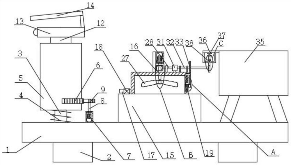
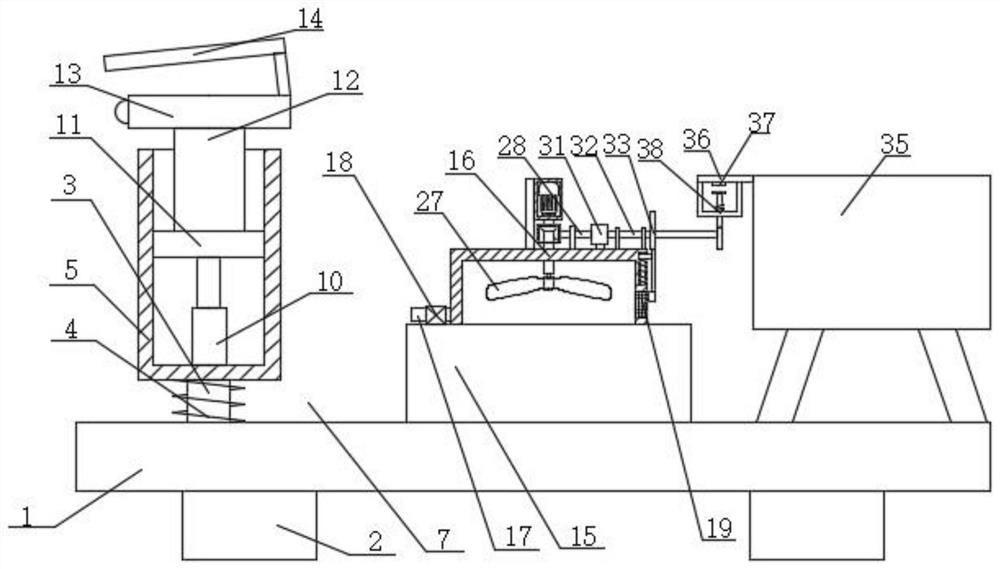
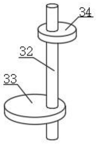
[0028] refer to Figure 1-6 , an unattended oilfield metering robot based on an image recognition system, including a base plate 1, two brackets 2 are symmetrically and fixedly installed on the bottom of the base plate 1, and an installation pipe 5 is installed on the top of the base plate 1 in rotation, and a mounting pipe 5 is fixedly installed on the installation pipe 5 Rack 6, slide plate 11 is installed slidingly in installation tube 5, and the top of slide plate 11 is fixedly installed with support plate 12, and the top of support plate 12 is fixedly installed with camera 13, and the top of camera 13 is fixedly installed with baffle plate 14, and installation pipe 5 An adjustment device is fixedly installed inside, a driving device is fixedly installed on the top of the bottom plate 1, a control box 15 is fixedly installed on the top of the bottom plate 1, an installation cover 16 is fixedly installed on the top of the control box 15, and a filter is fixedly installed on ...

Embodiment 2

[0039] refer to Figure 1-6 , an unattended oilfield metering robot based on an image recognition system, including a base plate 1, two brackets 2 are symmetrically and fixedly installed on the bottom of the base plate 1, and an installation pipe 5 is installed on the top of the base plate 1 in rotation, and a mounting pipe 5 is fixedly installed on the installation pipe 5 Rack 6, slide plate 11 is installed slidingly in installation tube 5, and the top of slide plate 11 is fixedly installed with support plate 12, and the top of support plate 12 is fixedly installed with camera 13, and the top of camera 13 is fixedly installed with baffle plate 14, and installation pipe 5 An adjustment device is fixedly installed inside, a driving device is fixedly installed on the top of the bottom plate 1, a control box 15 is fixedly installed on the top of the bottom plate 1, an installation cover 16 is fixedly installed on the top of the control box 15, and a filter is fixedly installed on ...


PUM


Abstract

The invention belongs to the technical field of metering robots, particularly relates to an unattended oil field metering robot based on an image recognition system. The following scheme aiming at the problems that an acquisition area is fixed when an existing robot is used, a device is easily damaged due to long-time loading, and the use efficiency is greatly reduced is provided. The unattended oil field metering robot comprises a bottom plate, two supports are symmetrically and fixedly mounted at the bottom of the bottom plate, a mounting pipe is rotatably mounted at the top of the bottom plate, a rack is fixedly mounted on the mounting pipe, a sliding plate is slidably mounted in the mounting pipe, a supporting plate is fixedly mounted at the top of the sliding plate, a camera is fixedly mounted at the top of the supporting plate, and a shielding plate is fixedly mounted at the top of the camera. An adjusting device is fixedly mounted in the mounting pipe, and a driving device is fixedly mounted at the top of the bottom plate. The unattended oil field metering robot based on the image recognition system is large in recognition and collection area, can be cooled continuously during use, and effectively prolongs the service life and improves the efficiency.

Description

technical field [0001] The invention relates to the technical field of metering robots, in particular to an unattended oilfield metering robot based on an image recognition system. Background technique [0002] An oil field refers to a specific area where crude oil is produced. Sometimes it is a general term for oil layers accumulated underground in a specific area. In a broad sense, several oil areas are collectively called an oil field. Due to the exchanges of staff and other specific personnel in the oil field, oil field metering robots are often used to help guard on duty through image recognition. [0003] However, when the existing robot is used, the collection area is fixed, and the device is easily damaged under long-term load, which greatly reduces the use efficiency. Contents of the invention [0004] The purpose of the present invention is to solve the shortcomings of the existing robot that the collection area is fixed when used, and the device is easily dama...

Claims


Application Information

Patent Timeline
Patent Type & Authority Applications(China)
IPC IPC(8): E21B47/002E21B47/00E21B41/00
CPCE21B47/00E21B47/002E21B41/00
Inventor 章斌
Owner 深圳市中科智清新能源科技有限公司
Why Eureka
Try Eureka