
All-in-one system and related method for fracking and completing a well which automatically installs sand screens for sand control immediately after fracking

a technology of sand control and fracking, which is applied in the direction of fluid removal, borehole/well accessories, construction, etc., can solve the problems of shortening the life of the pump, affecting the operation efficiency of the pump, and affecting the operation efficiency of the well

Active Publication Date: 2022-10-04
SC ASSET CORP
View PDF8 Cites 0 Cited by
  • Summary
  • Abstract
  • Description
  • Claims
  • Application Information

AI Technical Summary

Benefits of technology

This approach reduces time and cost by enabling immediate production after fracking, minimizes screen damage, and eliminates the need for multiple actuation members, allowing for efficient and cost-effective well completion with reduced downtime and increased production efficiency.

Problems solved by technology

As explained below, the introduction of large quantities of frac sand into a formation during the fracking process typically results in significant quantities of frac sand being entrained in the oil or gas which flows back into the wellbore for pumping to surface when oil is produced through opened frac ports in a wellbore.
Due to the abrasive nature of sand, deleterious and negative results occur during production, including additional increased and heavy wear on pump components within the well, greatly shortening pump life.
Downhole pumps, and even downhole pumps most resistive to sand abrasion such as progressive cavity pumps, are typically expensive.
Having to frequently replace such pumps results in increased costs not only in the replacing / refurbishing the pump and its components, but further in service rig time and costs in having to “trip out” of a well a downhole pump and “run back in” the production string with a new pump, to say nothing of the lost production and profits due to the well being “off line” during the time of such repairs.
Disadvantageously, however, the aforesaid two-step process having to frac, then trip out the frac string, and then run in a production string with pre-installed sand screens thereon results in considerable additional time and expense in tripping out the frac string, and thereafter running in the production string with elongate cylindrical screens installed thereon.
There is also an inherent risk of damaging the screens during “run in” of the production string in the wellbore.
Again, as in U.S. Pat. No. 9,976,394, two (2) actuating members need to be flowed downhole which not only consume time, but add additional cost.
Numerous other designs exist for moving a sliding sleeve so as to open a port and thereafter to cover the port, but do not provide for sand control or provision of screens.

Method used


Image

  • All-in-one system and related method for fracking and completing a well which automatically installs sand screens for sand control immediately after fracking
  • All-in-one system and related method for fracking and completing a well which automatically installs sand screens for sand control immediately after fracking
  • All-in-one system and related method for fracking and completing a well which automatically installs sand screens for sand control immediately after fracking

Examples


Embodiment Construction

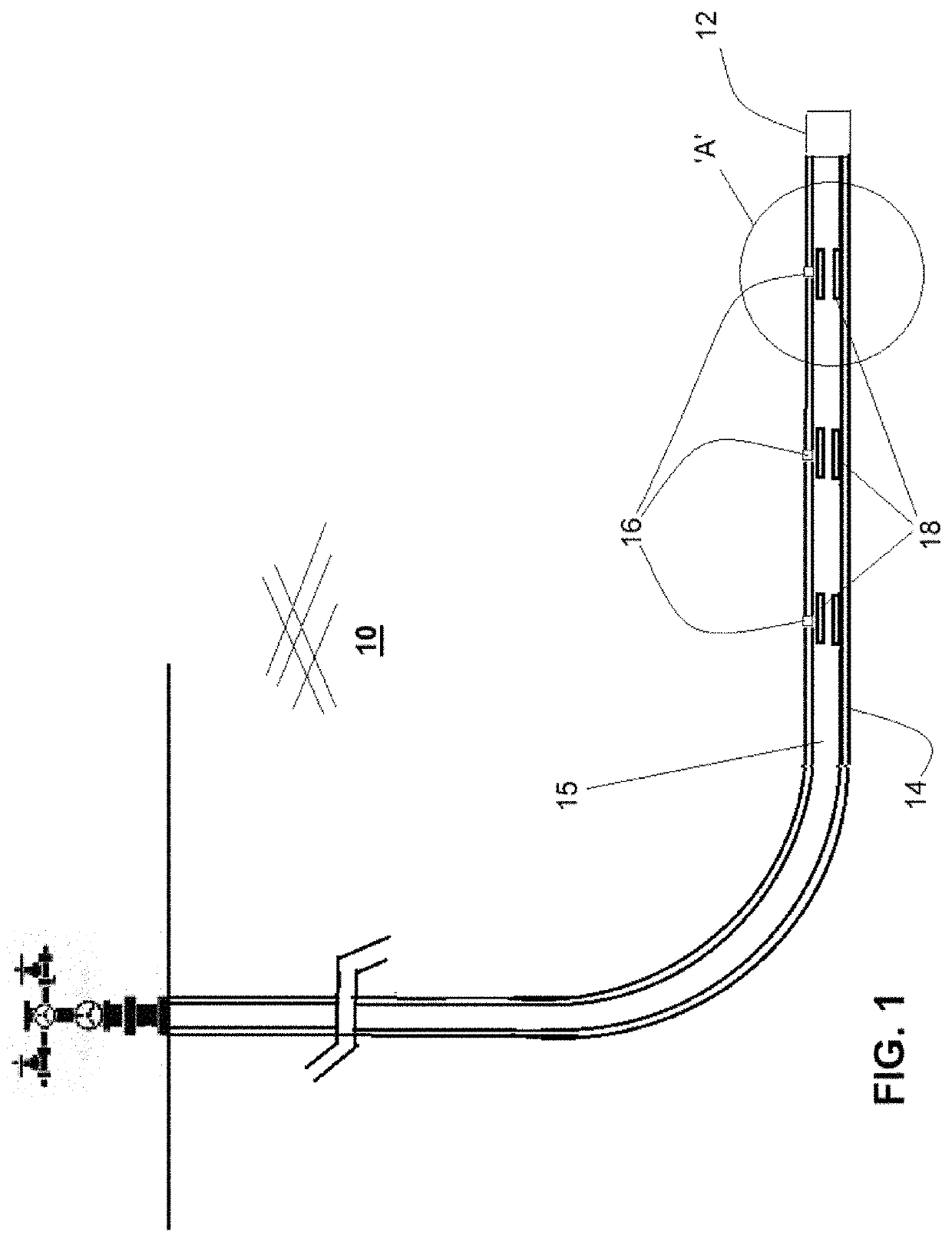
[0119]FIG. 1 is a schematic diagram of a typical wellbore 12 drilled within a hydrocarbon formation 10. A tubular liner 14 with an interior bore 15 is provided within such wellbore 12, with the tubular liner 14 having a plurality of longitudinally-spaced apart frac ports 16 spaced at longitudinal intervals therealong which provide, when open, fluid communication between the interior bore 15 and an exterior of the tubular liner 14.

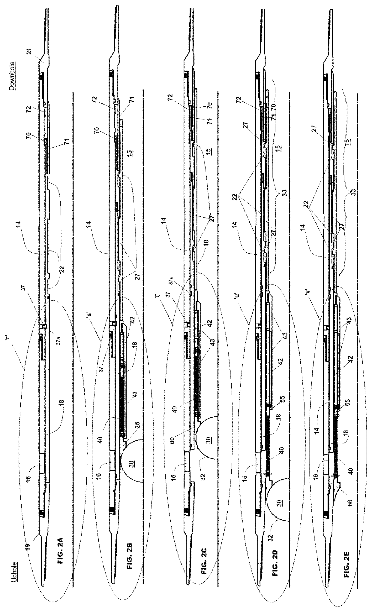
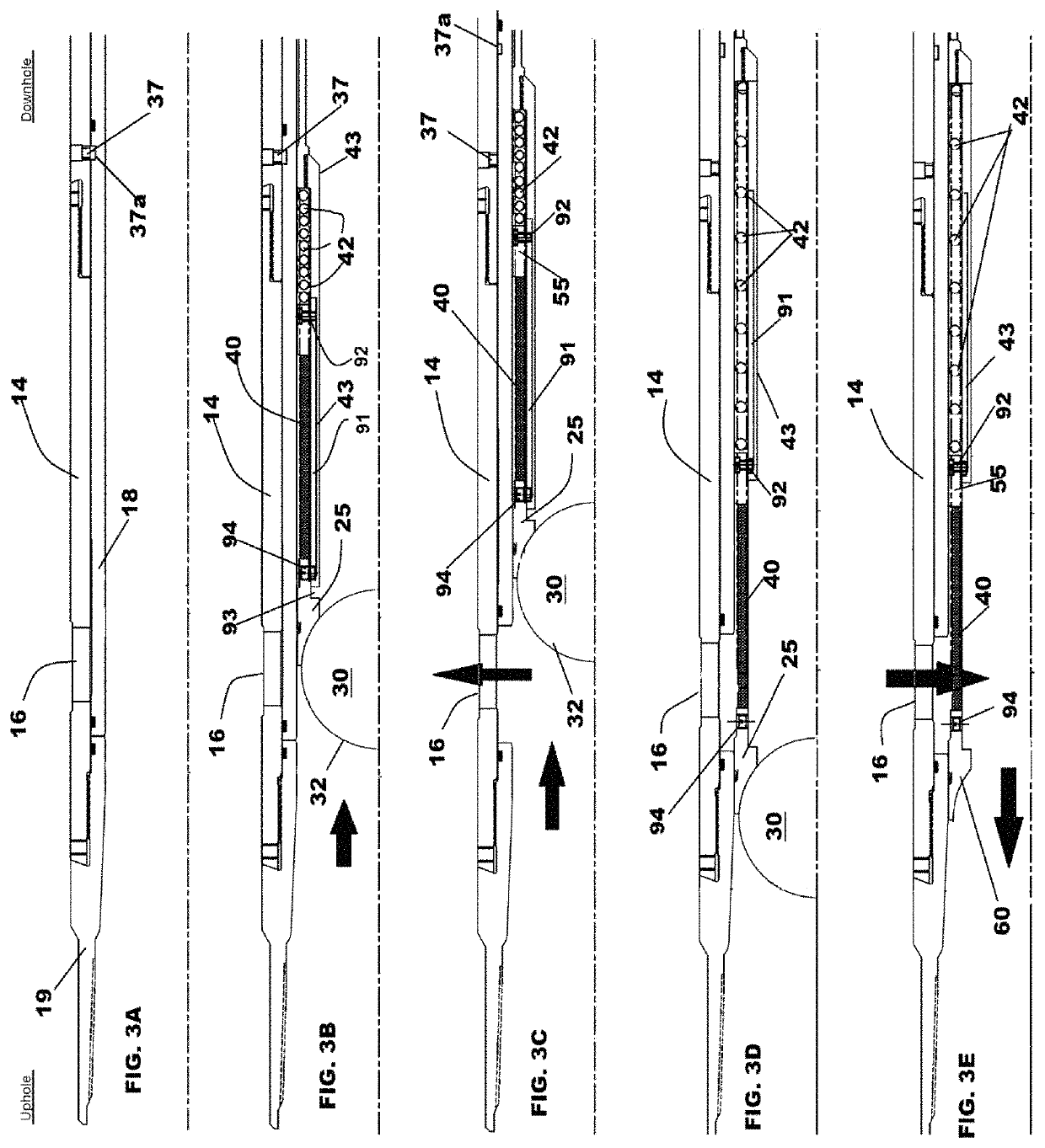
[0120]A plurality of cylindrical hollow sliding sleeve members 18 (“sliding sleeve”) are provided within interior bore 15 of and along tubing liner 14, each sliding sleeve 18 configured when in an initial closed position to cover a corresponding of said longitudinally spaced-apart frac ports 16, as shown for example in FIG. 1, 2A, 3A, and FIG. 4A. Each sliding sleeve member 18 is slidably movable longitudinally in the interior bore 15 to an open position to uncover a corresponding frac port 16, as shown for example in FIG. 1, 2C, 3C, and FIG. 4C.

[0121]As be...


PUM


Abstract

A system and method for fracking a hydrocarbon formation. An actuating member, flowable along a production string, is provided. A unique key portion thereon engages a desired sliding sleeve covering an associated port in the production string. Applying uphole fluid pressure causes the sliding sleeve and actuating member to move so as to uncover the associated port. After fracking and cessation of supply of pressurized fracturing fluid, a compressed spring on the actuating member decompresses so as to reposition a sand screen immediately beneath the port so as to prevent sand from flowing into the production string. Flowable insertion of additional “keyed” actuating members allows similar opening of additional successive uphole ports and fracking in the regions of such additional opened ports, with similar location of sand screens at each opened port. Plug members on each actuating member thereafter dissolve or are successively burst to thereby allow production.

Description

FIELD OF THE INVENTION[0001]The present invention relates to a system and method for fracking a hydrocarbon formation and completing a well for production, and more particularly relates to a system and method which immediately after completion of fracking automatically locates a sand screen at an opened port in a production string to prevent ingress of sand from the hydrocarbon formation to allow of subsequent immediate production.BACKGROUND OF THE INVENTION AND DESCRIPTION OF THE PRIOR ART[0002]After an oil or gas well is drilled within an underground hydrocarbon formation, the well and zones of interest need to be completed prior to production commencing.[0003]Part of the completion process typically firstly includes a fracking operation.[0004]Fracking involves injection of high pressure fluids (namely incompressible liquids, often containing proppants) into the hydrocarbon formation / reservoir to initiate fractures within the surrounding rock to increase porosity of “tight” format...

Claims


Application Information

Patent Timeline
Patent Type & Authority Patents(United States)
IPC IPC(8): E21B43/10E21B43/26E21B43/267E21B43/08E21B43/02
CPCE21B43/267E21B43/025E21B43/08E21B43/10E21B43/26E21B34/10E21B2200/06
Inventor CAMPBELL, SEAN P.ROJAS, DANIELSPELLER, DAVID
Owner SC ASSET CORP
Learn More