Image heating apparatus and image forming apparatus

a heating apparatus and image technology, applied in the field of image heating apparatus and image forming apparatus, can solve problems such as cost increas

Active Publication Date: 2022-11-01
CANON KK
View PDF8 Cites 0 Cited by
  • Summary
  • Abstract
  • Description
  • Claims
  • Application Information

AI Technical Summary

Benefits of technology

[0003]In the above mentioned configuration according to Japanese Patent Application Publication No. 2017-054071, each temperature detection element has an electric contact at the edge of the heater via a conductor, and is connected to a control substrate by an electric wire. For this electric wire, a flexible sheet, such as a flexible printed circuit (FPC) or a flexible flat cable (FFC) is used. The temperature detection element and the heater are connected by soldering the electric contacts. Use of the flexible sheet may improve assembly of the fixing apparatus since the routing of electric wires is easy. The connection portion where the flexible sheet is soldered to the electric contacts on the edge of the heater is normally reinforced by tape or adhesive, since this connection portion is strongly resistant to force in the shearing direction but is susceptible to force in the peeling direction. However, a heater which includes heating elements reaches high temperature and the tape or adhesive to be used must be resistant to high temperature, therefore concern is an increase in cost.
[0004]An object of the present invention is to provide a configuration that can reinforce the joining of the thermistor electrode of the heater and the flexible sheet without using tape and adhesive, and suppress solder peeling and electrode peeling.
[0024]As described above, according to the present invention, the peeling resistance of the flexible sheet, which is soldered to the thermistor electrode of the heater, can be reinforced without using tape or adhesive.

Problems solved by technology

The connection portion where the flexible sheet is soldered to the electric contacts on the edge of the heater is normally reinforced by tape or adhesive, since this connection portion is strongly resistant to force in the shearing direction but is susceptible to force in the peeling direction.
However, a heater which includes heating elements reaches high temperature and the tape or adhesive to be used must be resistant to high temperature, therefore concern is an increase in cost.

Method used


Image

  • Image heating apparatus and image forming apparatus
  • Image heating apparatus and image forming apparatus
  • Image heating apparatus and image forming apparatus

Examples


embodiment 1

Overview of Image Forming Apparatus

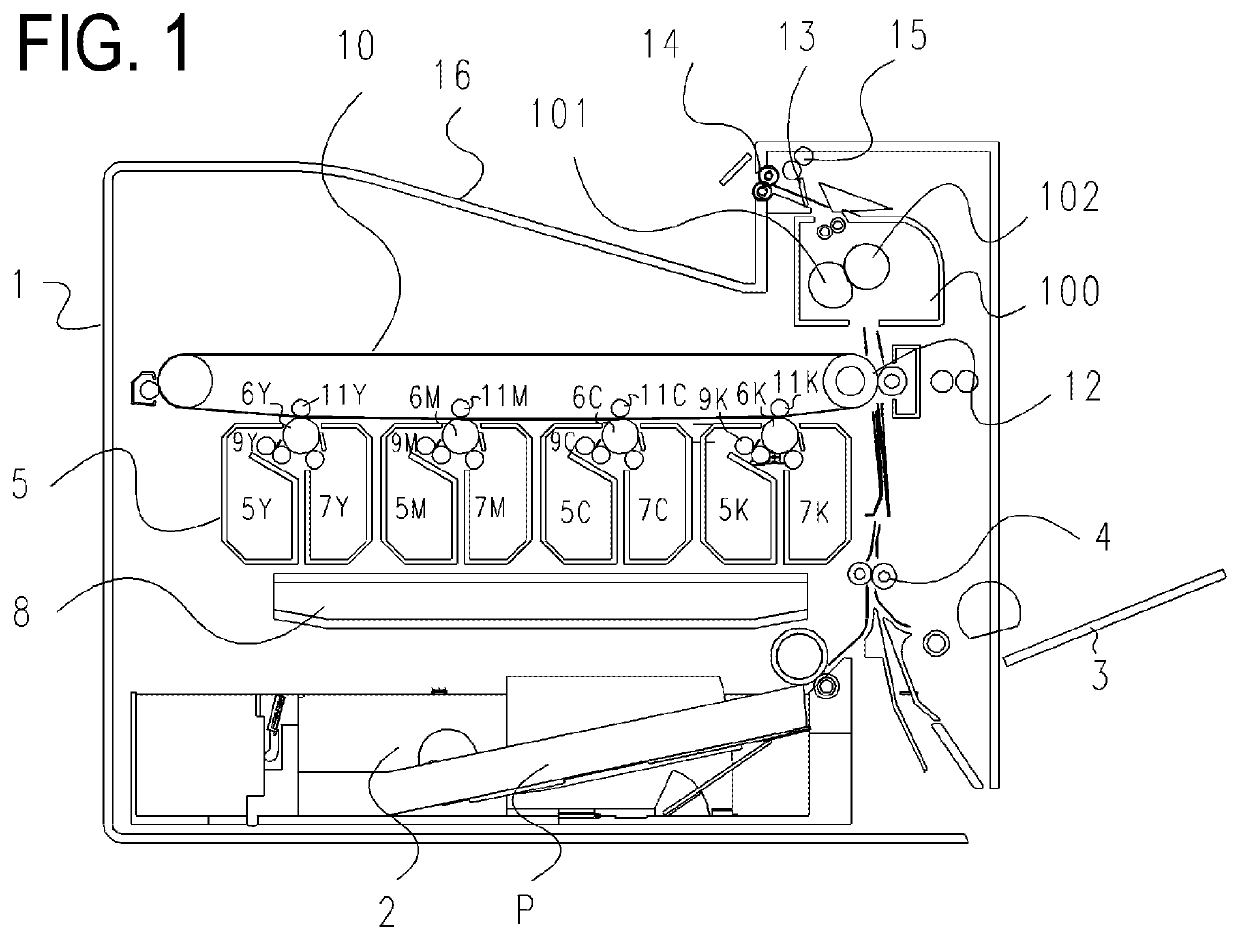
[0037]An image forming apparatus to which the present invention is applicable will be described first. FIG. 1 is a longitudinal cross-sectional view depicting a general configuration of a printer 1 equipped with a fixing apparatus, which is an example of an image heating apparatus according to the present invention. In a lower portion of the printer 1, a drawer type cassette 2 is stored. A manual feed portion 3 is disposed on the right side of the printer 1. Recording materials P can be loaded and stored in the cassette 2 and the manual feed portion 3 respectively, and the recording materials P are separated and fed one-by-one to a resist roller 4. The printer 1 includes an image forming portion 5 where image forming stations 5Y, 5M, 5C and 5K, corresponding to the colors yellow, magenta, cyan and black respectively, are disposed in a row in the lateral direction.

[0038]In the image forming portion 5, photosensitive drums 6Y, 6M, 6C and 6K (hereafte...

embodiment 2

[0051]A fixing apparatus according to Embodiment 2 of the present invention will be described next. A composing element the same as Embodiment 1 is denoted with the same reference sign, and description thereof is omitted.

[0052]FIG. 6A indicates a state before the U-shaped housing member 106b is installed, and FIG. 6B indicates a state after the U-shaped housing member 106b is installed. FIG. 7 indicates the heater holding member 105 in the state where the heater 200 is installed, viewed from the rear surface side of the heater. The housing member 106b includes a pair of contact portions 106b-1 and 106b-2 which extend in a second direction which is perpendicular to a first direction (first direction is a direction where the flexible sheet 107 overlaps with a part of the heater 200), and the contact portions 106b-1 and 106b-2 extend approximately parallel and face each other. The pair of contact portions of Embodiment 2 is constituted of the contact portion 106b-1 which comes into con...

embodiment 3

[0057]A fixing apparatus according to Embodiment 3 of the present invention will be described next. A composing element the same as Embodiment 1 or 2 is denoted with the same reference sign, and description thereof is omitted.

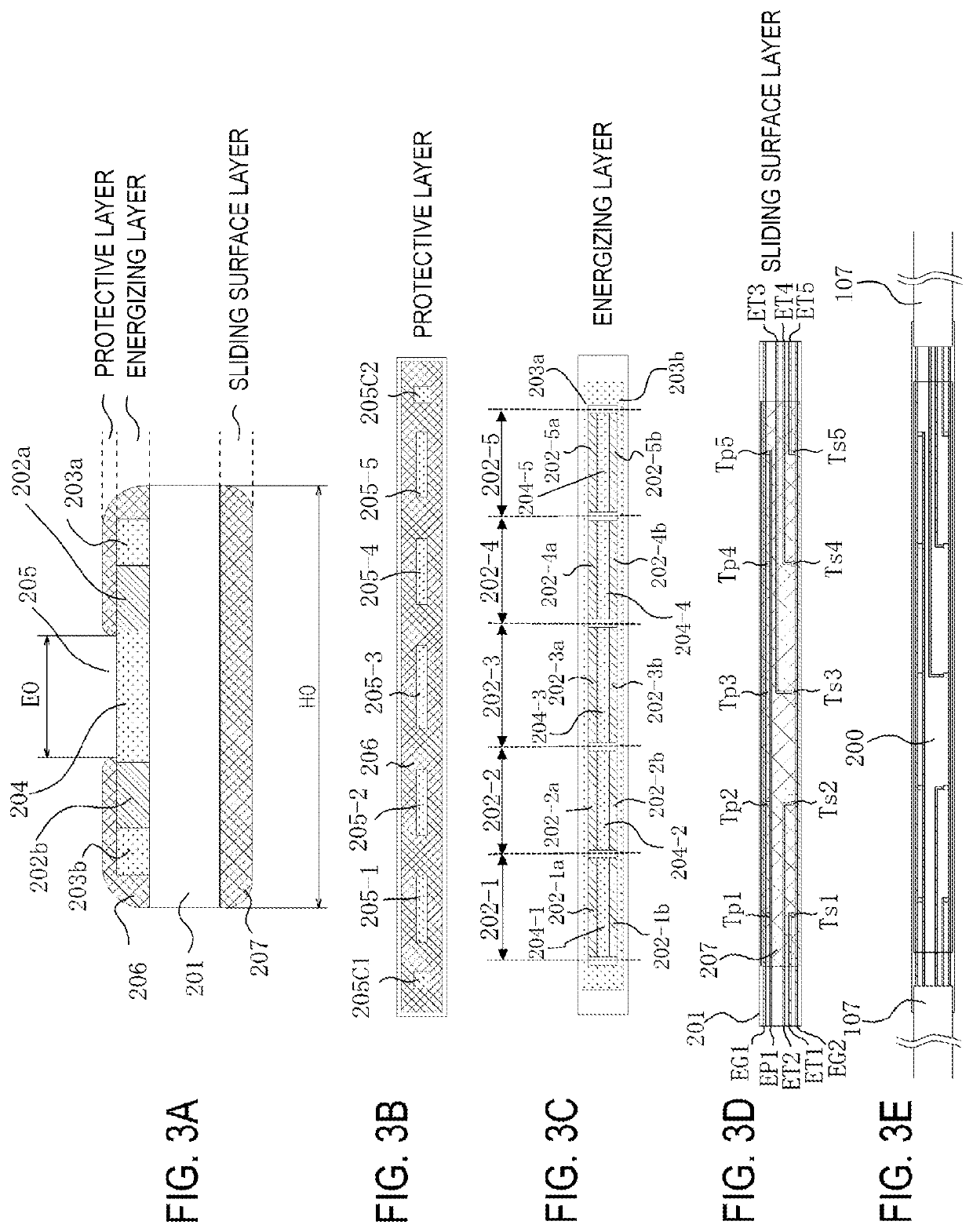
[0058]First the features of the heater to which the present invention is applied will be described with reference to FIGS. 10A to 10E. FIG. 10A is a cross-sectional view of the heater 200 in the shorter direction (direction perpendicular to the transporting direction of the recording material P). FIGS. 10B, 10C and 10D are plan views of each layer of the heater 200. FIG. 10E indicates a state where the flexible sheet 107 is joined with the electrodes on the edges of the heater.

[0059]On both edges of the sliding surface layer of the heater 200 in the longitudinal direction, and on both edges thereof in the shorter direction, the conductors LH1 to LH4 are formed. On both edges of the heater 200, a flexible sheet 107, constituted of a first sheet member which is c...


PUM


Abstract

Provided is an image heating apparatus comprising: a first rotating member; a second rotating member that forms a nip with the first rotating member so as to nip the recording material therebetween; a heater that heats the nip; a conductive sheet member that is disposed so as to overlap with a part of the heater; and a restricting member that restricts relative positions between the sheet member and the heater. The restricting member is configured so as to restrict a relative movement between the sheet member and the heater in a first direction, which is a direction where the sheet member overlaps with a part of the heater, and to allow the relative movement in a second direction which is perpendicular to the first direction. A reinforcing land, that joins the heater and the sheet member, is disposed in a position that is electrically isolated.

Description

BACKGROUND OF THE INVENTIONField of the Invention[0001]The present invention relates to an image heating apparatus of a fixing apparatus that is installed in an electrophotographic recording type image forming apparatus (e.g. copier, printer) and a glossing apparatus that improves a glass value of a toner image fixed on a recording material by reheating the toner image. In particular, the present invention is related to a temperature detection configuration of a heater used for thermal fixing in a fixing apparatus, which is an example of the image heating apparatus.Description of the Related Art[0002]A fixing apparatus that is installed in an image forming apparatus (e.g. copier, printer), which is an example of the above mentioned image heating apparatus, conventionally includes a film to transfer heat to a recording material and a heating resistor disposed on a ceramic substrate. Further, the fixing apparatus includes a heater that comes into contact with the inner surface of the ...

Claims


Application Information

Patent Timeline
Patent Type & Authority Patents(United States)
IPC IPC(8): G03G15/20
CPCG03G15/2053G03G2215/2035
Inventor SEKIMIZU, KOICHIYAMADA, KOICHIOBATA, SEIJINAMIKI, TERUHIKO
Owner CANON KK
Why Eureka
Try Eureka