Supercharge Your Innovation With Domain-Expert AI Agents!

Hammer tool

Active Publication Date: 2022-11-08
TANG CHOU IND CO LTD
View PDF4 Cites 2 Cited by
  • Summary
  • Abstract
  • Description
  • Claims
  • Application Information

AI Technical Summary

Benefits of technology

The present invention is a hammer tool with a head and handle. The head has a through hole and a connected hole. The handle has a connecting end that is inserted through the through hole and includes a protrusion in the connected hole. The second width of the connecting end is greater than the first width. The invention is not limited to the specific details and arrangements provided and is capable of other embodiments and methods of practice and carrying out the purposes of the invention. The patent text is intended to allow for quick understanding of the invention through the abstract and the technical effects of the invention.

Problems solved by technology

The problem is that the wooden handle wears, deforms and deteriorates easily after a long period of use.
Even worse, the head can detach from the handle.

Method used


Image

  • Hammer tool
  • Hammer tool
  • Hammer tool

Examples


Embodiment Construction

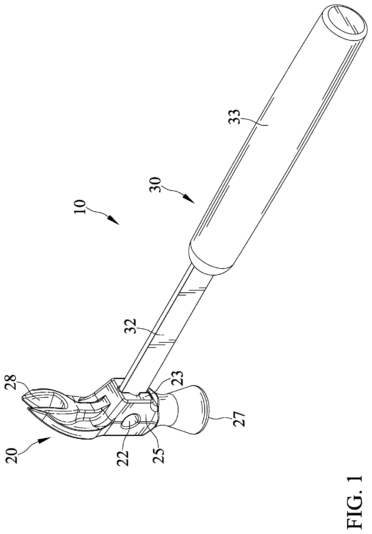
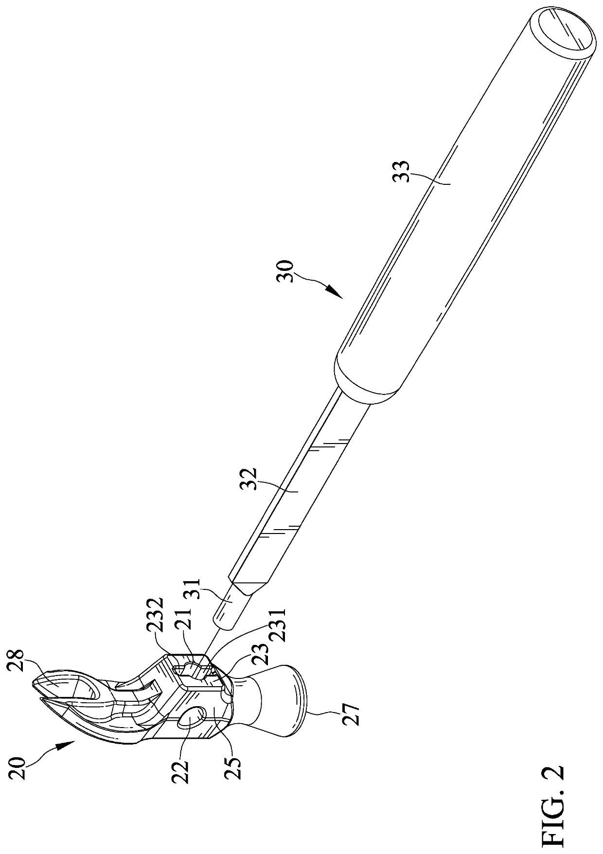
[0014]FIGS. 1 through 6 show a hammer tool 10 in accordance with the present invention. The hammer tool 10 includes a head 20 and a handle 30 tightly coupled to the head 20.

[0015]The head 20 defines a through hole 21 and a hole 22 connected to the through hole 21. The hole 22 extends transversely to the through hole 21. The through hole 21 is of a width W1 and the hole 22 is of a width greater than the width W1. The width W1 extends in a radial direction of the through hole 21, as shown in FIG. 3. The width W1 is the maximum width of the through hole 21. The through hole 21 and the hole 22 are circular holes.

[0016]The head 20 has an end 23 and an end 24 at opposite ends and a lateral side 25 and a lateral side 26 at opposite sides. The through hole 21 extends through the ends 23 and 24 of the head 20 and the hole 22 extends through the lateral sides 25 and 26 of the head 20 respectively.

[0017]The head 20 has a working portion 27 at an end and a working portion 28 at another end. The...


PUM


Abstract

A hammer tool includes a head and a handle tightly coupled to the head. The head defines a through hole and a hole connected to the through hole. The hole extends transversely to the through hole. The through hole is of a first width and the hole is of a width greater than the first width. The handle includes a connecting end inserted through the through hole. The connecting end is extruded after inserting through the through hole to include at least one positioning protrusion protruding into the hole. The connecting end is of a second width at where the at least one positioning protrusion is disposed. The second width is greater than the first width.

Description

BACKGROUND OF THE INVENTION1. Field of the Invention[0001]The present invention relates to a tool and, particularly, to a hammer tool with a strong connection between a head and a handle.2. Description of the Related Art[0002]TW Pat. No. 294100 discloses a hammer comprising a head and a handle and including a fixing device for securing the handle to the head. An end of the handle is connected to the head. The handle defines a groove receiving a fixing structure. The fixing structure includes a nail plug with at least one retaining tooth and a nail. The nail plug defines a through hole receiving the nail. The through hole has an inner inclined surface, an entrance at an end of the inclined surface and an outwardly expanding section at the other end. The expanding section has a smaller diametrical size than the nail plug. The nail plug can be forced to expand by the nail so as to secure the handle to the head. The nail plug has a plurality of notches that facilities the expansion ther...

Claims


Application Information

Patent Timeline
Patent Type & Authority Patents(United States)
IPC IPC(8): B25D1/04
CPCB25D1/045B25D2250/051B25G3/18
Inventor LIOU, MOU-TANG
Owner TANG CHOU IND CO LTD
Features
  • R&D
  • Intellectual Property
  • Life Sciences
  • Materials
  • Tech Scout
  • Unparalleled Data Quality
  • Higher Quality Content
  • 60% Fewer Hallucinations
Learn More