Common mode filter for reducing differential mode signal converting to common mode signal

a common mode and signal technology, applied in the field of common mode filters, to achieve the effect of reducing the mode conversion characteristic (scd) and improving the noise reduction performance of the product, and upgrading the practicality of the present invention

Active Publication Date: 2022-11-08
TAI TECH ADVANCED ELECTRONICS CO LTD
View PDF1 Cites 0 Cited by
  • Summary
  • Abstract
  • Description
  • Claims
  • Application Information

AI Technical Summary

Benefits of technology

[0009]Therefore, the present invention can effectively reduce the mode conversion characteristic (Scd), and can also improve the noise reduction performance of the product; thereby greatly upgrading the practicality of the present invention; and the present invention has a simple process, therefore the product yield can be further upgraded to achieve the effect.

Problems solved by technology

However, the existing common mode filter has a problem that the mode conversion characteristic (also known as Scd) is high when the differential mode signal converts to the common mode signal; that is, after the differential mode signal is input to the common mode filter, a higher proportion of the differential mode signal is converted into a common mode signal (noise) and output; as a result, the existing common mode filter cannot achieve better noise reduction performance.

Method used


Image

  • Common mode filter for reducing differential mode signal converting to common mode signal

Examples


Embodiment Construction

[0011]The following descriptions are exemplary embodiments only, and are not intended to limit the scope, applicability or configuration of the invention in any way. Rather, the following detailed description provides a convenient illustration for implementing exemplary embodiments of the invention.

[0012]Various changes to the described embodiments may be made in the function and arrangement of the elements described without departing from the scope of the invention as set forth in the appended claims.

[0013]The foregoing and other aspects, features, and utilities of the present invention will be best understood from the following detailed description of the preferred embodiments when read in conjunction with the accompanying drawings.

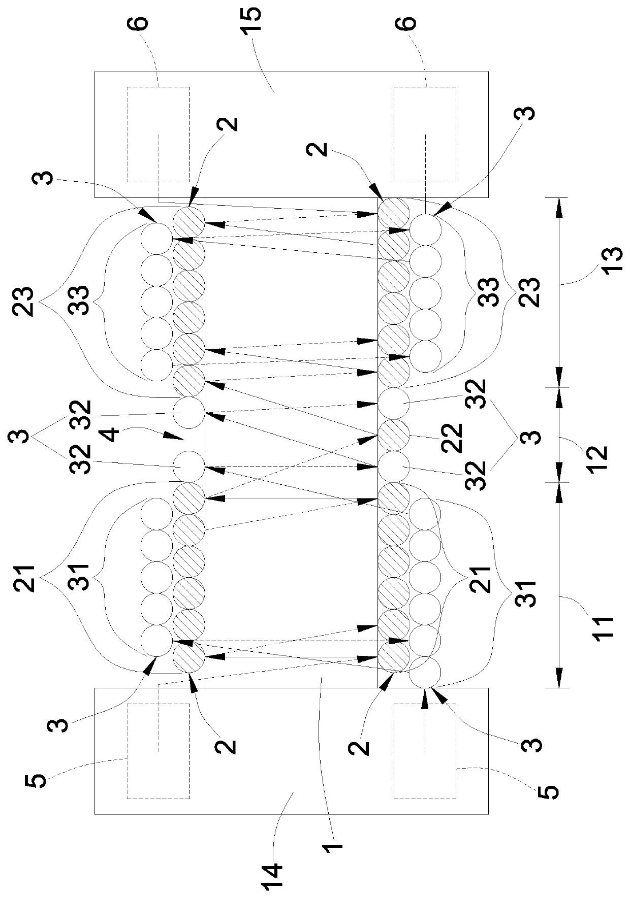
[0014]Please refer to FIG. 1, the present invention provides a common mode filter for reducing differential mode signal converting to common mode signal; which comprises: core-cylinder 1, a first coil 2 and a second coil 3; wherein the core-cylinder 1 i...


PUM

PropertyMeasurementUnit
winding areaaaaaaaaaaa
areaaaaaaaaaaa
magnetic fieldaaaaaaaaaa

Abstract

A common mode filter for reducing differential mode signal converting to common mode signal comprising: a core-cylinder, a first coil, and a second coil; wherein two ends of the core-cylinder respectively extend and set with a first flange and a second flange; wherein m1, m2, and m3 turns and n1, n2, and n3 turns are respectively and sequentially wound and set on the first winding portion, the second winding portion, and the third winding portion of the first winding area, the second winding area, and the third winding area of the first coil and the second coil. Therefore, the present invention can effectively reduce the mode conversion characteristic (Scd), and can also improve the noise reduction performance of the product; thereby greatly upgrading the practicality of the present invention; and the present invention has a simple process, therefore the product yield can be further upgraded to achieve the effect.

Description

(a) TECHNICAL FIELD OF THE INVENTION[0001]The present invention is a common mode filter, and especially relates a common mode filter for reducing differential mode signal converting to common mode signal.(b) DESCRIPTION OF THE PRIOR ART[0002]An ordinary common mode filter is mainly provided with a first coil and a second coil wound around an iron core, and the ends of the first coil and the second coil are respectively connected with the terminal electrodes of the iron core. The filtering principle is that when a noise current such as a common mode current passes through the common mode filter, the common mode current generates a magnetic field in the same direction on the first coil and the second coil; thereby increasing the inductive reactance of the first coil and the second coil. By making the common mode filter appear as high impedance, a high common mode impedance can be generated, and the common mode current can be attenuated, thereby achieving the purpose of filtering out c...

Claims


Application Information

Patent Timeline
Patent Type & Authority Patents(United States)
IPC IPC(8): H01F17/04H03H7/42H03H1/00H01F17/00
CPCH01F17/045H03H1/00H03H7/427H01F2017/0093H03H2001/005H03H2001/0092H01F27/006H01F27/2823
Inventor HSIEH, MING-YENSHEN, PAO LINYANG, HSIANG CHUNG
Owner TAI TECH ADVANCED ELECTRONICS CO LTD
Why Eureka
Try Eureka