Fastener and installation method for very thin sheets

a technology of fasteners and sheets, applied in the direction of threaded fasteners, manufacturing tools, mechanical equipment, etc., can solve the problems of high cost and waste, and many known self-clinching fasteners cannot be installed in relatively thick sheets or components

Active Publication Date: 2022-11-15
PENN ENG & MFG CORP
View PDF24 Cites 1 Cited by
  • Summary
  • Abstract
  • Description
  • Claims
  • Application Information

AI Technical Summary

Benefits of technology

[0006]In one preferred embodiment, the present invention provides clinch-in fasteners that can be installed by clinch-in fastening in holes of very thin workpieces, such as metal sheets, using novel tooling and installation methods. For example, the fasteners can be clinched in a blind hole as shallow as 0.014 inches deep. The clinch-in fastener is preferably used with an installation tool that displaces sheet material against and over structural features of the fastener that resist axial pull-out and torque. Moreover, the inventive fastener and installation minimize and / or eliminate marking or blemishes on the opposite side of the panel during installation.
[0007]Usually, self-clinching fasteners for thin panels require very tight tolerances. To ease this requirement, preferred embodiments of the fastener have a lead installation shank that has a chamfered lead surface and an outer diameter that interferes slightly with the side of the hole.
[0022]The inventive fastener, tooling and installation methods provide many advantages over the prior art. For example, embodiments of the invention provide one or more of the following features and advantages.
[0023]The displacer is eliminated from the fastener. Instead, it is incorporated into the installation tool. As a result, the minimum hole depth in the workpiece is reduced. This construction also effectively eliminates the undercut in prior art self-clinching fasteners.
[0028]The axial component of the high installation force on prior art self-clinching fasteners can cause excess stress and be carried through to the cosmetic face. In preferred embodiments of the invention, the amount of axial force needed to cold deform the workpiece is reduced by using a rotating wedge. Torque is employed to plow metal over the fastener shank. The amount of axial force is reduced by reducing the cross-sectional area of material being pressed into the panel, by redirecting the axial force into the horizontal orientation with the displacers, and deforming material radially toward the fastener.
[0029]Because the installation will require both torque and axial force for installation, equipment must be employed that has this capability. CNC milling machines are used to cut the shallow, flat bottomed installation holes. According to the invention, the same machine, in the same operation, then changes tools automatically and installs a fastener into the hole that was just created. This method eliminates the need for separate installation equipment and the need to handle parts through two operations. This method creates a great economic benefit for the assembly of small consumer electronics.

Problems solved by technology

Therefore, many known self-clinching fasteners can only be installed in relatively thick sheets or components.
This process is costly and wasteful.

Method used


Image

  • Fastener and installation method for very thin sheets
  • Fastener and installation method for very thin sheets
  • Fastener and installation method for very thin sheets

Examples


Embodiment Construction

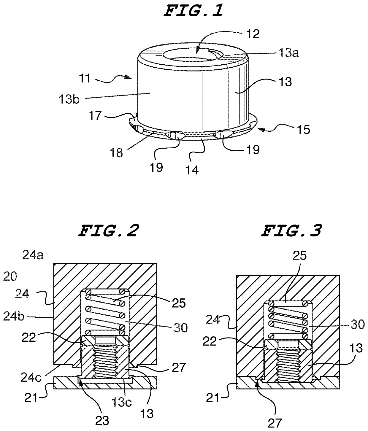
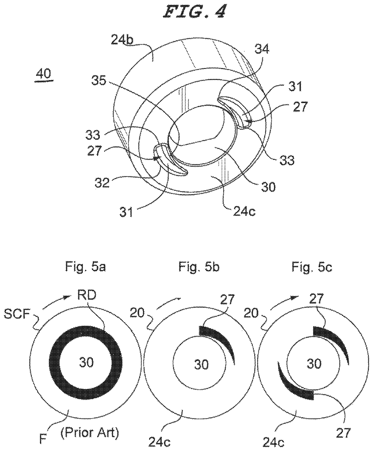
[0042]“Self-clinching fastener” means any device, usually threaded, that, when pressed into ductile metal, displaces the host material around the mounting hole, causing it to cold flow into a specially designed annular recess in the shank or pilot of the fastener.”“Clinch-in” fastener means any device, usually threaded, that, can be mechanically fastened in a blind receiving hole of a metal workpiece by cold deforming the metal surrounding the hole into contact with the device. “Clinch-in fastening” as used with reference to a fastener and metal workpiece is used in its broadest send to mean the process of joining the fastener to the workpiece (without additional components) using a tool to plastically deform the workpiece into contact with the fastener to form a mechanical interlock between the fastener and the workpiece.

[0043]A fastener in accordance with a preferred embodiment of the invention is shown in FIGS. 1-3 and 6, and is designated generally by reference numeral 11. Refer...


PUM

PropertyMeasurementUnit
angleaaaaaaaaaa
perimeteraaaaaaaaaa
thicknessaaaaaaaaaa

Abstract

A clinch-in fastener with a cylindrical body having a top, a bottom, sides and an axial internal bore. The fastener has a single shank at the bottom end of the body having a top surface orthogonal to the bore and a chamfer tapering to the bottom of the body. The top surface of the shank is adapted for receiving the cold flow of material surrounding a receiving hole of a workpiece. The shank may have a plurality of notches in its outermost edge that extend through both the top surface of the shank and the chamfer. The bore of the fastener extends completely through the fastener body from top to bottom and may be threaded. A fastener installation system having a tool with means for affixation to a rotary and vertically reciprocal element of an industrial machine. The tip of the tool has a distal end face with at least one arcuate displacer adapted for deforming a workpiece as the tool rotates and is pressed against the workpiece. A bore within the tip holds a fastener installed by the tool. The displacer is vertically and radially tapered along an arcuate ridge centered about the axial bore. The width of the displacer is also tapered to a point.

Description

CROSS-REFERENCE TO RELATED APPLICATIONS[0001]This application is a non-provisional patent application of provisional patent application 62 / 503,582 entitled “Concealed Head Fastener for Very Thin Sheets” filed May 9, 2017, and provisional patent application 62 / 625,310 entitled “Floating Pin Assembly”, filed Feb. 1, 2018, both of which are incorporated herein by reference, and priority from both of which is hereby claimed.FIELD OF THE INVENTION[0002]The present invention relates to fasteners, and methods of installing, that can be fastened to very thin sheet material. In one preferred embodiment, the fastener is a concealed head standoff fastener that is installed with a rotary punch.BACKGROUND OF THE INVENTION[0003]There are many fastening applications that require installation of a threaded fastener in a blind hole. For example, this installation method is often used for assembling components of a waterproof apparatus. However, more often than not, this installation method is used w...

Claims


Application Information

Patent Timeline
Patent Type & Authority Patents(United States)
IPC IPC(8): F16B37/06B23P19/06B21D39/03
CPCB23P19/064B21D39/031F16B37/068B21J15/12B21J15/38B21J15/32B21J15/04B21J15/02
Inventor MALONEY, MICHAEL JBENTRIM, BRIAN G.
Owner PENN ENG & MFG CORP
Why Eureka
Try Eureka