Fastener and Installation Method for Very Thin Sheets

a technology of fasteners and thin sheets, applied in the direction of threaded fasteners, manufacturing tools, mechanical equipment, etc., can solve the problems of high cost and waste, and many known self-clinching fasteners cannot be installed in relatively thick sheets or components, so as to reduce the amount of axial force needed to cold deform the workpiece, reduce the cross-sectional area of material, and reduce the amount of axial force

Active Publication Date: 2019-11-14
PENN ENG & MFG CORP
View PDF0 Cites 3 Cited by
  • Summary
  • Abstract
  • Description
  • Claims
  • Application Information

AI Technical Summary

Benefits of technology

[0028]The axial component of the high installation force on prior art self-clinching fasteners can cause excess stress and be carried through to the cosmetic face. In preferred embodiments of the invention, the amount of axial force needed to cold deform the workpiece is reduced by using a rotating wedge. Torque is employed to plow metal over the fastener shank. The amount of axial force is reduced by reducing the cross-sectional area of material being pressed into the panel, by redirecting the axial force into the horizontal orientation with the displacers, and deforming material radially toward the fa

Problems solved by technology

Therefore, many known self-clinching fasteners can only be installed in r

Method used


Image

  • Fastener and Installation Method for Very Thin Sheets
  • Fastener and Installation Method for Very Thin Sheets
  • Fastener and Installation Method for Very Thin Sheets

Examples


Embodiment Construction

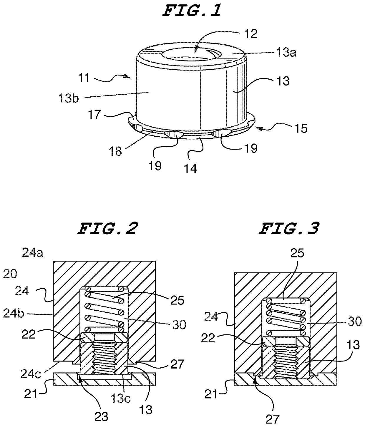
[0042]“Self-clinching fastener” means any device, usually threaded, that, when pressed into ductile metal, displaces the host material around the mounting hole, causing it to cold flow into a specially designed annular recess in the shank or pilot of the fastener.”“Clinch-in” fastener means any device, usually threaded, that, can be mechanically fastened in a blind receiving hole of a metal workpiece by cold deforming the metal surrounding the hole into contact with the device. “Clinch-in fastening” as used with reference to a fastener and metal workpiece is used in its broadest send to mean the process of joining the fastener to the workpiece (without additional components) using a tool to plastically deform the workpiece into contact with the fastener to form a mechanical interlock between the fastener and the workpiece.

[0043]A fastener in accordance with a preferred embodiment of the invention is shown in FIGS. 1-3 and 6, and is designated generally by reference numeral 11. Refer...


PUM

PropertyMeasurementUnit
Angleaaaaaaaaaa
Lengthaaaaaaaaaa
Forceaaaaaaaaaa

Abstract

A clinch-in fastener with a cylindrical body having a top, a bottom, sides and an axial internal bore. The fastener has a single shank at the bottom end of the body having a top surface orthogonal to the bore and a chamfer tapering to the bottom of the body. The top surface of the shank is adapted for receiving the cold flow of material surrounding a receiving hole of a workpiece. The shank may have a plurality of notches in its outermost edge that extend through both the top surface of the shank and the chamfer. The bore of the fastener extends completely through the fastener body from top to bottom and may be threaded. A fastener installation system having a tool with means for affixation to a rotary and vertically reciprocal element of an industrial machine. The tip of the tool has a distal end face with at least one arcuate displacer adapted for deforming a workpiece as the tool rotates and is pressed against the workpiece. A bore within the tip holds a fastener installed by the tool. The displacer is vertically and radially tapered along an arcuate ridge centered about the axial bore. The width of the displacer is also tapered to a point.

Description

CROSS-REFERENCE TO RELATED APPLICATIONS[0001]This application is a non-provisional patent application of provisional patent application 62 / 503,582 entitled “Concealed Head Fastener for Very Thin Sheets” filed May 9, 2017, and provisional patent application 62 / 625,310 entitled “Floating Pin Assembly”, filed Feb. 1, 2018, both of which are incorporated herein by reference, and priority from both of which is hereby claimed.FIELD OF THE INVENTION[0002]The present invention relates to fasteners, and methods of installing, that can be fastened to very thin sheet material. In one preferred embodiment, the fastener is a concealed head standoff fastener that is installed with a rotary punch.BACKGROUND OF THE INVENTION[0003]There are many fastening applications that require installation of a threaded fastener in a blind hole. For example, this installation method is often used for assembling components of a waterproof apparatus. However, more often than not, this installation method is used w...

Claims


Application Information

Patent Timeline
IPC IPC(8): B23P19/06B21D39/03
CPCB23P19/064B21D39/031B21J15/12B21J15/38B21J15/32B21J15/04B21J15/02F16B37/068
Inventor MALONEY, MICHAEL JBENTRIM, BRIAN G.
Owner PENN ENG & MFG CORP
Why Eureka
Try Eureka