Supercharge Your Innovation With Domain-Expert AI Agents!

Lighting device and power switching circuit

a technology of power switching circuit and light source, which is applied in the direction of circuit arrangement, emergency power supply arrangement, electrical apparatus, etc., can solve the problem of unstability of the light sour

Active Publication Date: 2022-11-15
APUTURE IMAGING IND CO LTD
View PDF10 Cites 0 Cited by
  • Summary
  • Abstract
  • Description
  • Claims
  • Application Information

AI Technical Summary

Benefits of technology

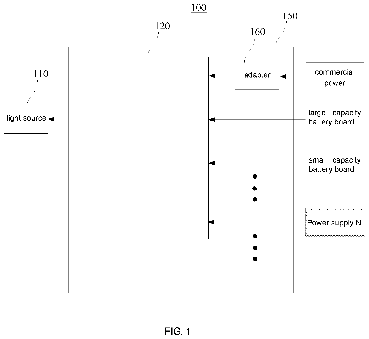
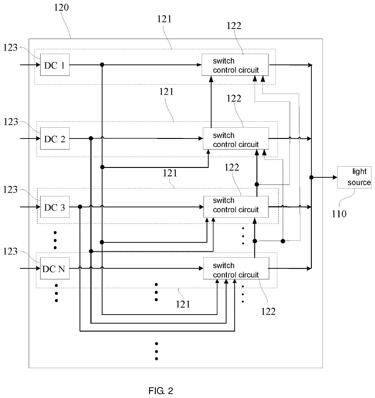
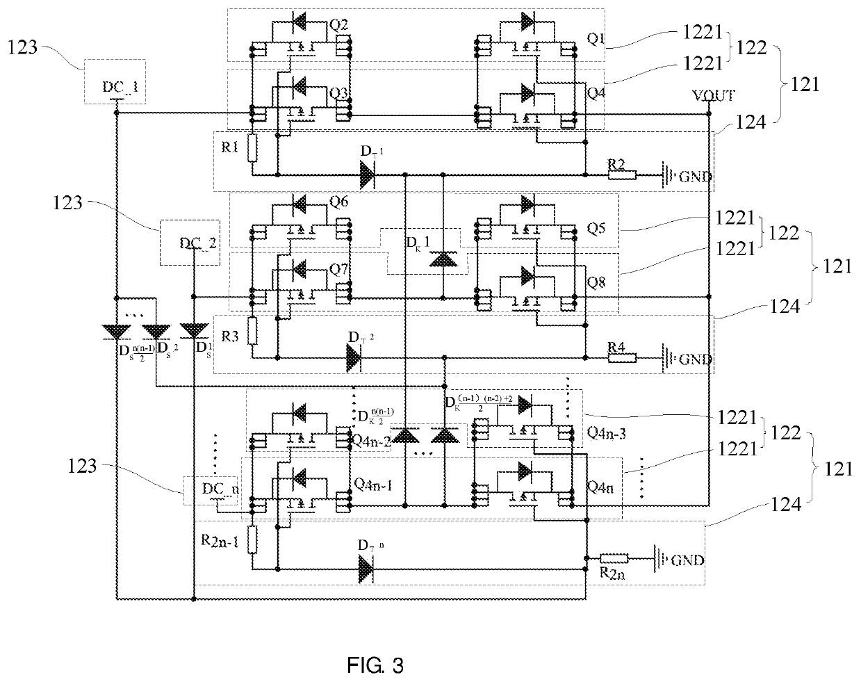
The patent text describes a circuit that controls power distribution to a light source. It includes multiple power input circuits, and a switch control circuit that selectively activates or deactivates each circuit. This ensures that power is only supplied to the desired light source, and prevents power from flowing backwards through the circuit. This results in a more stable and efficient lighting device.

Problems solved by technology

However, when a battery supplies power to the light source, an power input terminal of an existing power switching circuit electrically connected with the utility power and the light source may be in a conducting state, to cause electric current supplied by the battery to flow reversely into an power input terminal of the utility power through the power input terminal of the power switching circuit, and cause the lighting device to operate unstably.

Method used


Image

  • Lighting device and power switching circuit
  • Lighting device and power switching circuit
  • Lighting device and power switching circuit

Examples


Embodiment Construction

[0034]Technical solutions in embodiments of the present disclosure will be described clearly and completely in combination with the drawings in the embodiments of the present disclosure. Obviously, the embodiments described are only part of the embodiments of the present disclosure, not all embodiments. According to the embodiments in the present disclosure, all other embodiments obtained by those of skill in the art that the embodiments described herein without making creative work belong to the protection scope of the present disclosure.

[0035]In description of the disclosure, it should be understood that, orientational relationships represented by directional terms mentioned in the present disclosure, such as center, longitudinal, transverse, length, width, thickness, up, down, front, back, left, right, vertical, horizontal, top, bottom, inside, outside, clockwise, anticlockwise, etc., are orientational relationships based on the drawings, and are merely for the convenience of des...


PUM


Abstract

A lighting device includes a light source and a power switching circuit including a plurality of power input circuits. Each of the power input circuits includes a power input terminal and a switch control circuit connected in series between the power input terminal and the light source. A control terminal of Nth switch control circuit controls the Nth switch control circuit to be turned off according to a first electrical signal input by first to (N-1)th power input terminals. The control terminal of the Nth switch control circuit controls the Nth switch control circuit to be turned on according to a second electrical signal being input by Nth power input terminal, and controls the first to (N-1)th switch control circuits to be turned off. The N is a positive integer greater than 1. A power switching circuit is also provided.

Description

FIELD OF INVENTION[0001]The present disclosure generally relates to a lighting device, and a power switching circuit.BACKGROUND OF INVENTION[0002]Generally, a light source of a lighting device is powered by a variety of power supplies, such as utility power and batteries. When one of the power supplies is turned off, the power supply is switched by a power switching circuit, so that the light source is powered by another power supply, thus to stably ensure the lighting device operate.[0003]In order to reduce electricity cost of the lighting device and improve service life of the lighting device, for the power switching circuit utility power is preferred to supply power. When the utility power is turned off, the power switching circuit switches to battery or other power supplies to supply power.[0004]However, when a battery supplies power to the light source, an power input terminal of an existing power switching circuit electrically connected with the utility power and the light sou...

Claims


Application Information

Patent Timeline
Patent Type & Authority Patents(United States)
IPC IPC(8): H05B47/10
CPCH05B47/10H02J9/061H05B47/00
Inventor HUANG, YIZHOU, XIANGJUNTONG, KUN
Owner APUTURE IMAGING IND CO LTD
Features
  • R&D
  • Intellectual Property
  • Life Sciences
  • Materials
  • Tech Scout
  • Unparalleled Data Quality
  • Higher Quality Content
  • 60% Fewer Hallucinations
Learn More