Paint tray with roller-holding means

a technology of roller-holding and paint tray, which is applied in the direction of coating, other artistic work equipment, decoration, etc., can solve the problems of difficult to achieve, particularly strong and relatively undeformable, and suffers in spite of drawbacks, etc., to achieve stable and robust

Inactive Publication Date: 2001-08-16
FRANPIN
View PDF0 Cites 27 Cited by
  • Summary
  • Abstract
  • Description
  • Claims
  • Application Information

AI Technical Summary

Benefits of technology

0007] The invention sets out to resolve those drawbacks, i.e. to propose a tray having a roller-holding arrangemen

Problems solved by technology

Although such an arrangement presents the advantage that the roller drips into the tray and not outside it or onto the handle, it nevertheless suffers f

Method used


Image

  • Paint tray with roller-holding means
  • Paint tray with roller-holding means
  • Paint tray with roller-holding means

Examples


Embodiment Construction

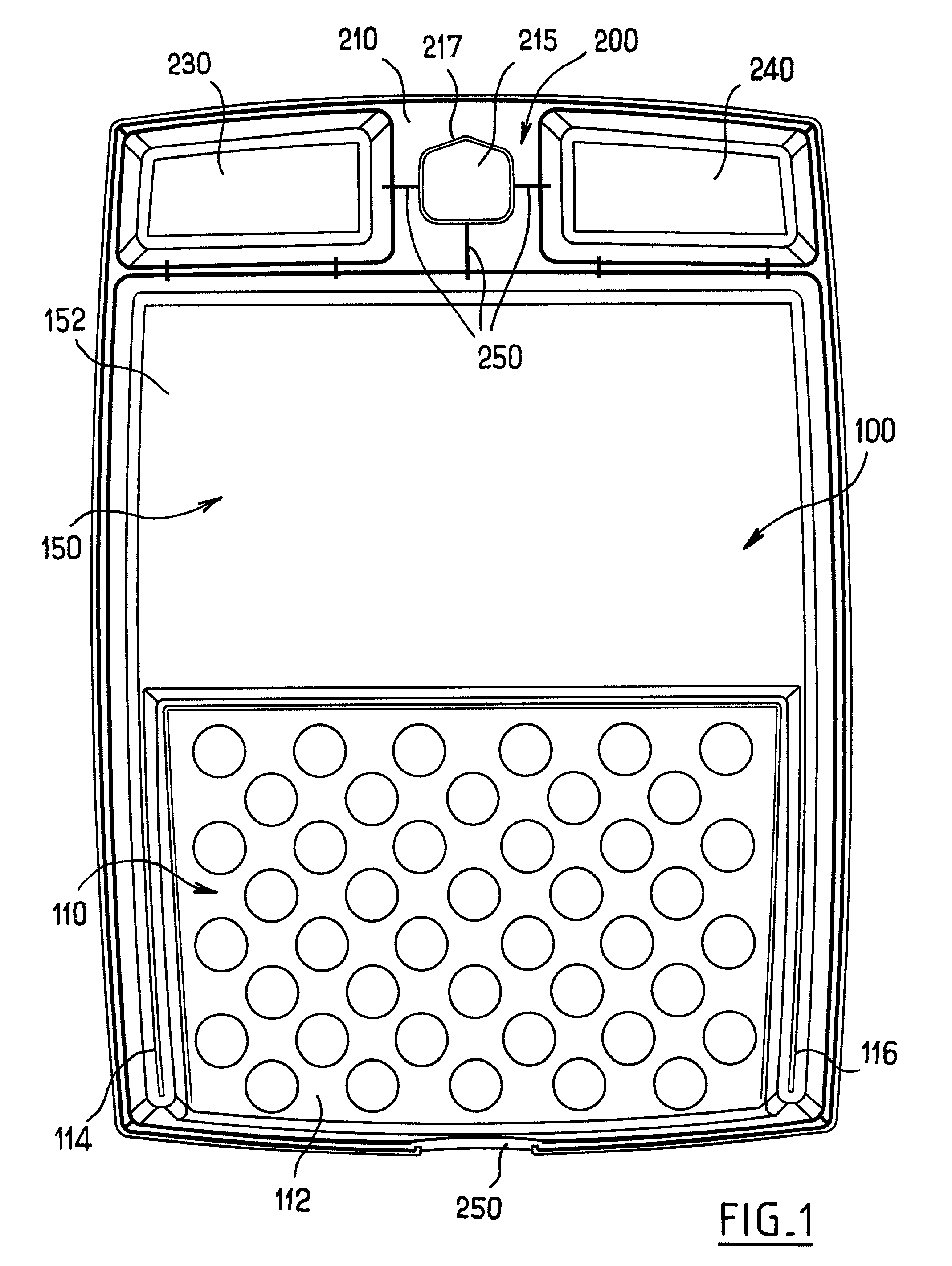
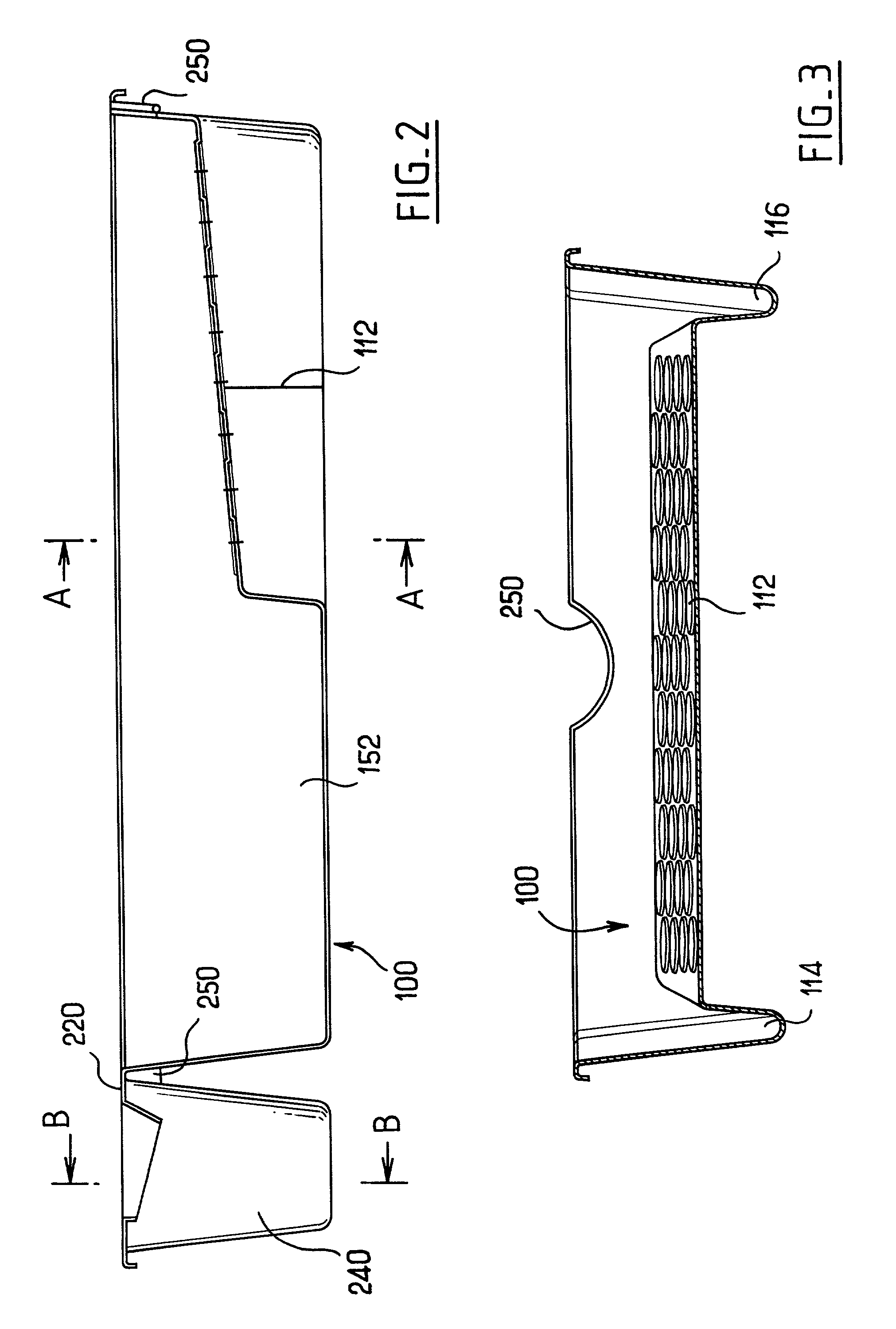
[0016] The present tray is a one-piece molded tray comprising mainly a pan 100 and means for holding the roller when not in use. The pan 100 is made up of two halves 110 and 150 respectively forming a paint spreading slope 112 and a paint trough 152 extending from the bottom of the slope.

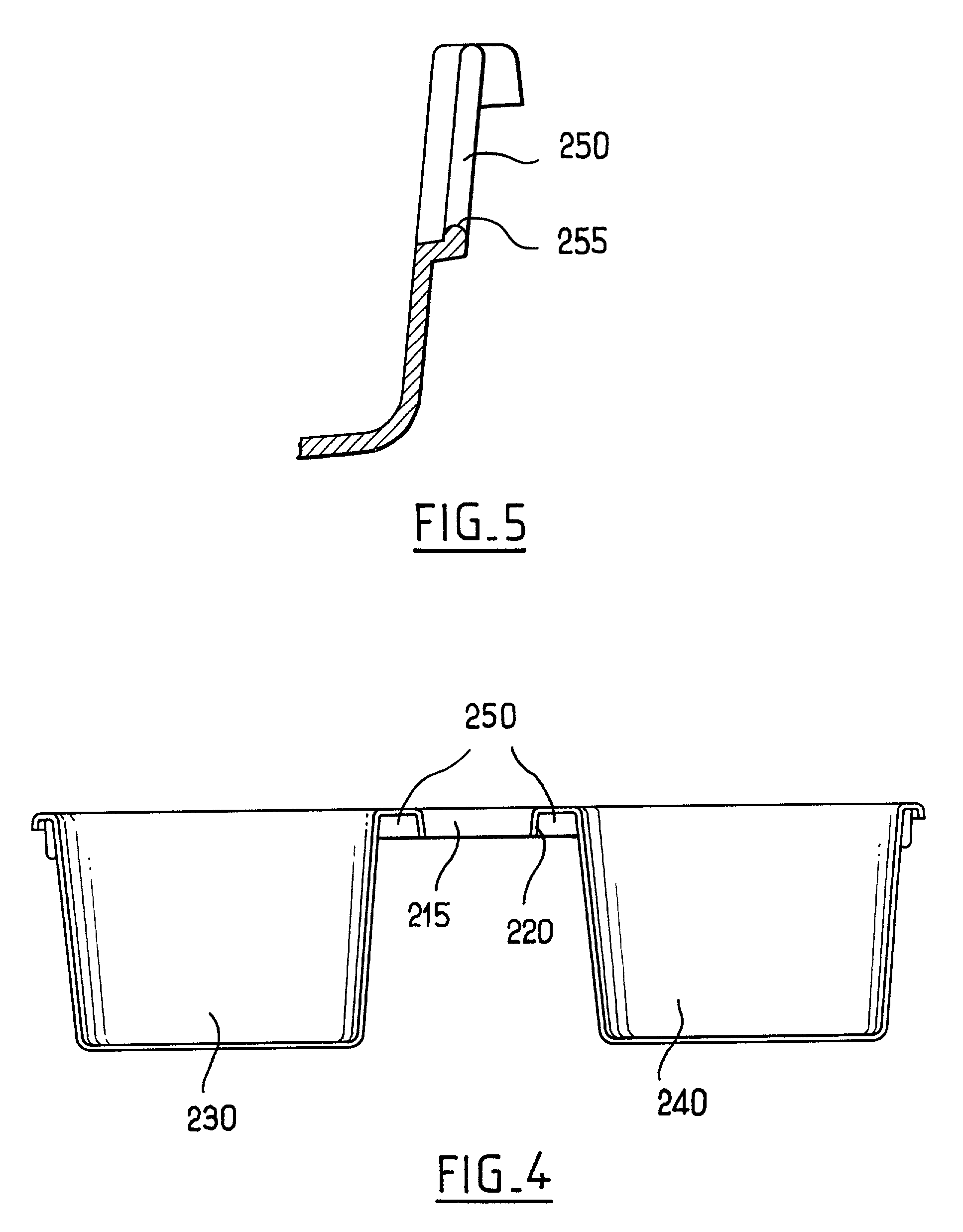
[0017] The pan 100 is rectangular in shape, being bordered by four substantially vertical walls. The wall that is on the side of the trough 152 that is remote from the slope 112 is extended out from the trough by an arrangement 200 for holding paint brushes and rollers.

[0018] In this example, the arrangement 200 extends over the entire width of the pan 100, with its top portion extending horizontally level with the tops of the walls of the pan 100.

[0019] In its central portion, the arrangement has a horizontal wall 210 lying in the horizontal plane of the top edges of the pan 100. This horizontal wall 210 has a central orifice 215 with the outline of the orifice being extended downwards so as to for...


PUM


Abstract

The invention provides a paint tray for a paint roller, the tray comprising a paint pan and holding arrangements for a roller comprising a handle and a rotary roller proper, the holding arrangements being provided to hold the roller in a selected position in which at least the lowest portion of the roller proper is in a position to drip into the paint pan, wherein the holding arrangements are designed to co-operate essentially with the handle of the roller.

Description

[0001] The present invention relates to paint trays for applicator rollers.[0002] Such trays are generally rectangular and typically comprise a sloping wall which goes down to a trough containing paint.[0003] After the roller has been dipped in the paint, the slope serves to spread the paint uniformly over the roller. Excess paint runs down the slope and back into the paint trough.[0004] Proposals are made in document FR 2 322 754 to fit one edge of the tray with a series of vertical pegs, each serving to hold a roller that is engaged thereon vertically.[0005] Proposals have also been made in document U.S. Pat. No. 4,025,205 to fit a side wall of the tray with an element that is specially designed to hold the roller in a position where the roller proper extends horizontally over the paint.[0006] Although such an arrangement presents the advantage that the roller drips into the tray and not outside it or onto the handle, it nevertheless suffers from drawbacks. The holding element mus...

Claims


Application Information

Patent Timeline
IPC IPC(8): B44D3/12
CPCB44D3/126
Inventor LALLEMENT, FREDERICFIEVET, PASCAL
Owner FRANPIN
Why Eureka
Try Eureka