Chip-Removing Tool

a cutting tool and chip technology, applied in the field of cutting inserts, can solve the problems of reducing the work efficiency so as to improve the cooling effect or cooling/lubricating effect of the cutting tool, the effect of accelerating the boring operation

Inactive Publication Date: 2011-05-05
KENNAMETAL INC
View PDF9 Cites 7 Cited by
  • Summary
  • Abstract
  • Description
  • Claims
  • Application Information

AI Technical Summary

Benefits of technology

[0021]Claims 14 and 15 relate to a cutting tool, in particular a boring tool having a cutting insert according to the invention and advantageously a tool seat according to the invention. The combination of cutting insert and tool seat used is very space-saving. This enables the areas in the region of the tool cutting lips to be used in another way. For example, it is possible to form cooling passages in the cutting tool, said cooling passages having an enlarged cross section compared with the prior art. In this way, the cooling effect or the cooling / lubricating effect of the cutting tool can be significantly improved. In particular in the case of boring tools, this can considerably accelerate the boring operation.

Problems solved by technology

A disadvantage in this case is the large amount of space required by the clamping shoe.
In addition, it is not possible to arrange an effective surface of the tool, for example a main or secondary cutting lip, in the region of the clamping shoe.
A disadvantage in this case is the weakening in the strength of the tool which inevitably accompanies the making of the screwing passage.

Method used


Image

  • Chip-Removing Tool
  • Chip-Removing Tool
  • Chip-Removing Tool

Examples


Embodiment Construction

[0029]The same parts in the various configurations are always provided with the same reference numerals below.

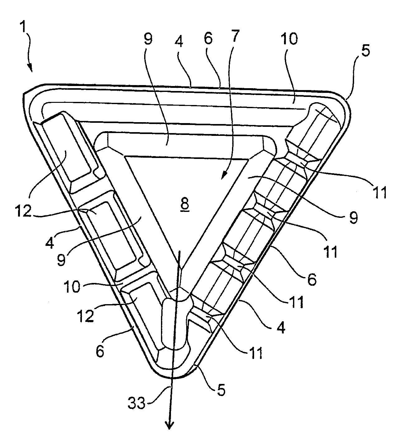
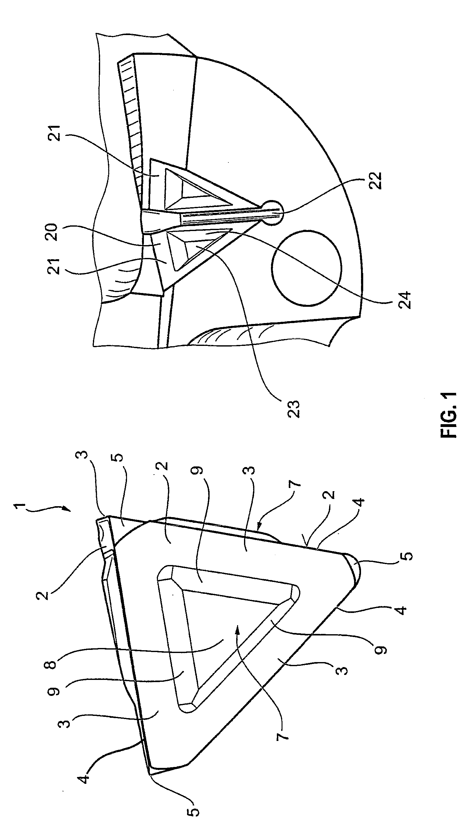
[0030]The cutting insert 1 shown on the left in FIG. 1 is configured as a Platonic solid. Each of its base areas 2 has the geometry of an equilateral triangle having a triangle interior angle of 60°. The regular tetrahedron has four congruent base areas 2 with the geometry of an equilateral triangle. The edges of the triangle sides 3 form the cutting edges 4 of the cutting insert 1, which are effective as cutting lips. The nodal points of in each case three abutting triangle sides 3 form in each case a cutting lip corner 5. The cutting insert 1 has four such cutting lip corners 5. These cutting lip corners 5 can be configured for the respective machining purpose. For example, corner rounding or a bevel can be provided. A cutting lip bevel 6 is provided in the region of the cutting edges 4 for stabilizing the cutting lips. Furthermore, the cutting edges 4 can be sharp-edged o...


PUM

PropertyMeasurementUnit
angleaaaaaaaaaa
angle of inclinationaaaaaaaaaa
interior anglesaaaaaaaaaa

Abstract

A cutting insert has the geometry of a tetrahedron with triangle base areas wherein each triangle base area has a tetrahedral frustum as a clamping body for fixing the cutting insert in a tool seat of a carrier tool. Additionally, a tool seat for the cutting insert includes clamping jaws to secure the cutting insert.

Description

BACKGROUND OF THE INVENTION[0001]The invention relates to a cutting insert for a cutting tool, a tool seat for such a cutting insert, and a cutting tool having such a cutting insert, in particular a boring tool.[0002]In the field of machining technology, it is known not to form the cutting lip of a tool in one piece with the tool, but rather to design it as a separate component in the form of a cutting tip, an indexable cutting tip or a cutting body as cutting insert. Such a cutting body is known, for example, from DD 157 314 A.[0003]The cutting inserts are used in special tools and in tools for producing relatively large lot sizes. As soon as the cutting lips located on the cutting insert are worn, the cutting insert is removed from the tool and replaced by a new cutting insert. There are therefore no downtimes for the regrinding of the tool. In addition, such cutting inserts are especially suitable for cutting lips made of special materials, for example carbide, cermet or ceramic,...

Claims


Application Information

Patent Timeline
Patent Type & Authority Applications(United States)
IPC IPC(8): A61B17/10
CPCB23B27/16B23B51/048B23B2200/0423B23B2200/081B23B2200/321B23B2200/3627Y10T407/194B23B2205/12B23C5/22Y10T407/1924Y10T407/23Y10T407/24Y10T408/9098B23B2205/02B23B51/00
Inventor MERGENTHALER, PETER KARL
Owner KENNAMETAL INC
Why Eureka
Try Eureka