Optical printer with micromirror device

a technology of optical printer and micro-mirror, which is applied in the field of optical printers, can solve problems such as deteriorating the quality of photographs

Inactive Publication Date: 2001-08-23
FUJIFILM CORP +1
View PDF0 Cites 11 Cited by
  • Summary
  • Abstract
  • Description
  • Claims
  • Application Information

AI Technical Summary

Benefits of technology

[0011] According to a preferred embodiment, the correction device accumulates fluctuation values detected by the detection device, to correct the image projecting position on the photosensitive material on the basis of an accumulated fluctuation value. The correction device also controls the paper advancing device to change the length of advancement of the photosensitive material when the accumulated fluctuation value goes beyond a range within which the image projecting position is correctable by the displacement of the spatial light modulator, so as to reduce the accumulated fluctuation value to be within the range.

Problems solved by technology

The gap or the overlap respectively appears as a white stripe or a black stripe, and deteriorates the quality of the photograph.

Method used


Image

  • Optical printer with micromirror device
  • Optical printer with micromirror device
  • Optical printer with micromirror device

Examples


Embodiment Construction

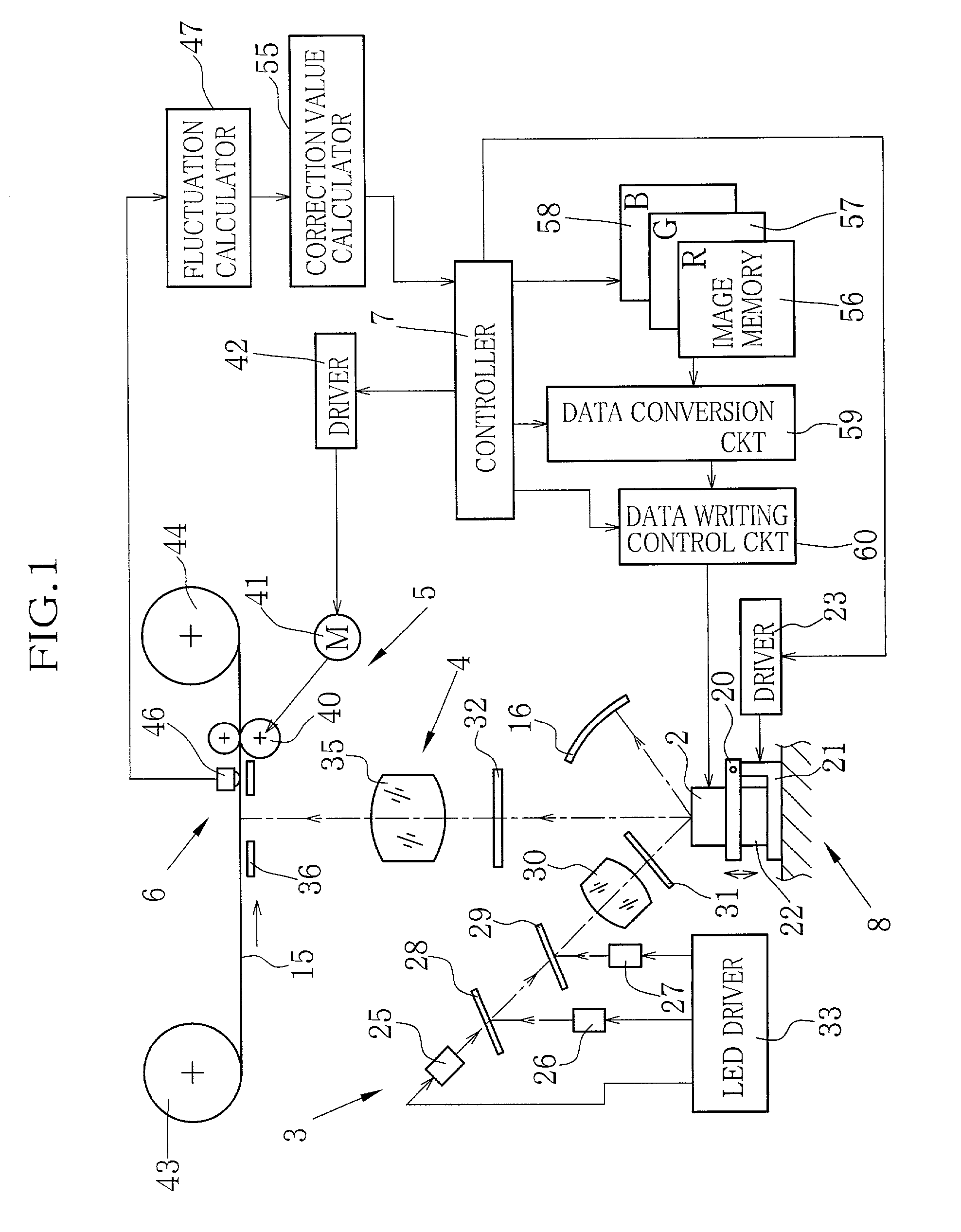
[0024] In FIG. 1, an optical printer according to an embodiment of the present invention has a digital micromirror device (DMD) 2 as a spatial light modulator, a light source section 3 for illuminating the DMD 2, an image projecting optical system 4, a paper advancing section 5, a detector section 6 for detecting fluctuation in advanced length of a color photographic paper 15, a controller 7 and an exposure position correcting section 8.

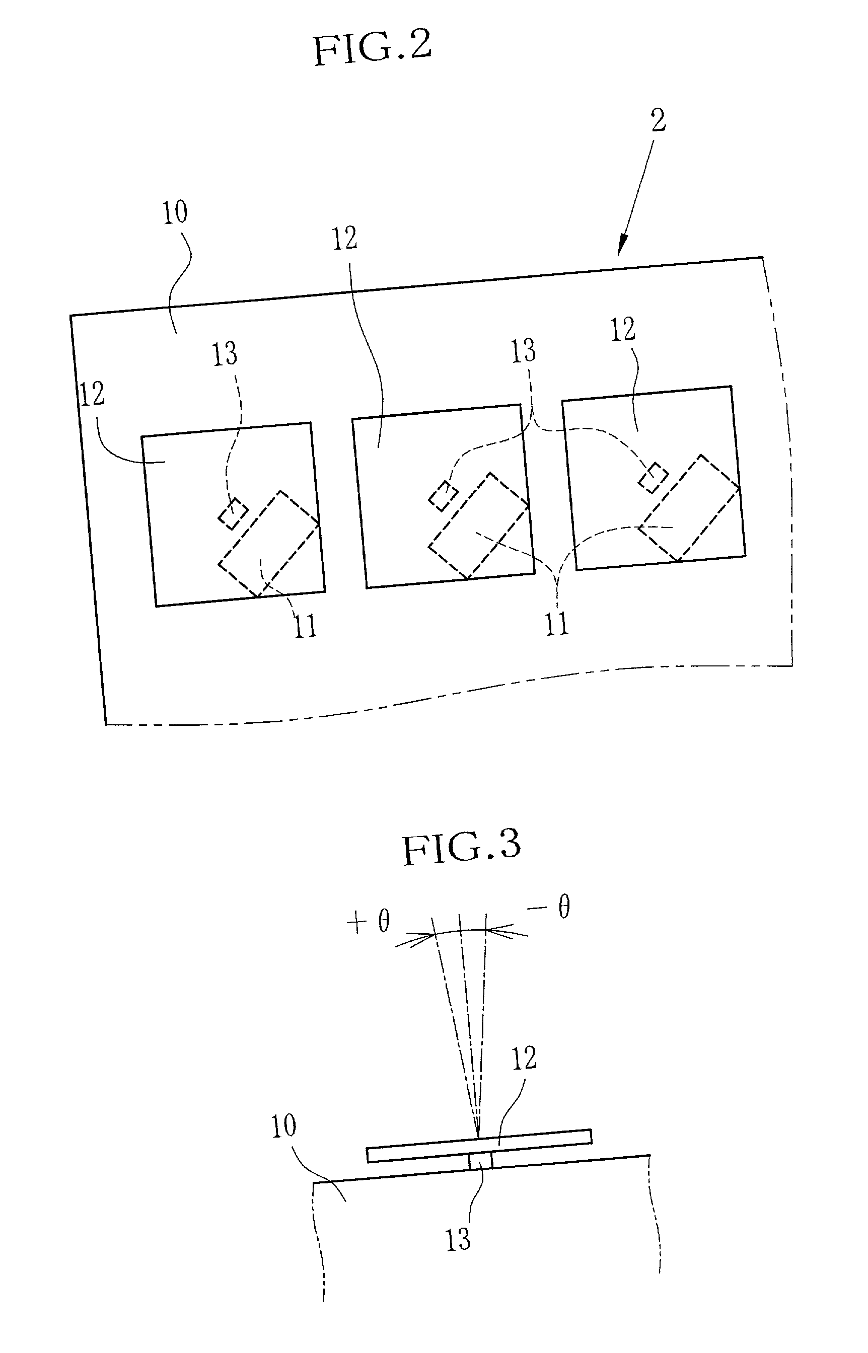
[0025] As shown in FIG. 2, the DMD 2 has a large number of memory cells 11 formed on a statistic RAM (SRAM) 10. Above each of the memory cells 11 is disposed a micromirror 12, a very small square mirror chip, e.g. 16 .mu.m on a side, made of conductive metal foil, e.g. aluminum foil. As shown in FIG. 3, the micromirror 12 is supported at its center on a post 13 so as to be able to tilt about the post 13. The micromirror 12 is tilted by an electrostatic force generated between the memory cell 11 and the micromirror 12. The memory cell 11, the micromir...


PUM


Abstract

An optical printer has a DMD as a spatial light modulator. An optical image corresponding to a fraction of a picture frame is projected from the DMD onto a photographic paper at a predetermined time interval. The photographic paper is advanced intermittently by a length corresponding to an exposure area for one optical image. A fluctuation value from a set advanced length for one advancing step is detected at each advancing step and accumulated. The DMD is mounted on a swinging plate whose angle is controllable by a piezoelectric element, to shift the exposure position on the photographic paper. In accordance with an accumulated fluctuation value, drive voltage to the piezoelectric element is changed from a reference value to correct the exposure position so as to print the picture frame without any gap or overlap between the fractions.

Description

[0001] 1. Field of the Invention[0002] The present invention relates to an optical printer with a spatial light modulator constituted of a micromirror device having a large number of very small mirrors with variable reflecting direction.[0003] 2. Background Arts[0004] Optical printers print pictures, including characters and drawings, on photosensitive materials, such as photographic paper. Of the optical printers, color photographic printers that project an optical image of a picture frame from negative photographic film onto photographic paper have been widely used. Recently, digital optical printers have been developed and used in practice that drive a display device in accordance with digital image data to print a picture by projecting printing light beams or an optical image from the display device onto a photosensitive material. As the digital optical printers, there are CRT type, Laser type, LCD type, micromirror type and so forth.[0005] The micromirror type optical printer u...

Claims


Application Information

Patent Timeline
Patent Type & Authority Applications(United States)
IPC IPC(8): H04N1/113B41J2/465G02B26/08G03B27/32H04N1/04H04N1/23
CPCB41J2/465G02B26/0841
Inventor ENOMOTO, JUNNAKAMURA, HIROAKIFUKAZAWA, JUN
Owner FUJIFILM CORP
Why Eureka
Try Eureka