Method of performing array-based hybridization assays using thermal inkjet deposition of sample fluids

Inactive Publication Date: 2001-08-23
AGILENT TECH INC
View PDF0 Cites 352 Cited by
  • Summary
  • Abstract
  • Description
  • Claims
  • Application Information

AI Technical Summary

Problems solved by technology

Although effective, there are drawbacks associated with each of the above techniques.
First, each of the above techniques requires the deposition of relatively large sample volumes, e.g. greate

Method used


Image

  • Method of performing array-based hybridization assays using thermal inkjet deposition of sample fluids

Examples


Example

EXAMPLE 1

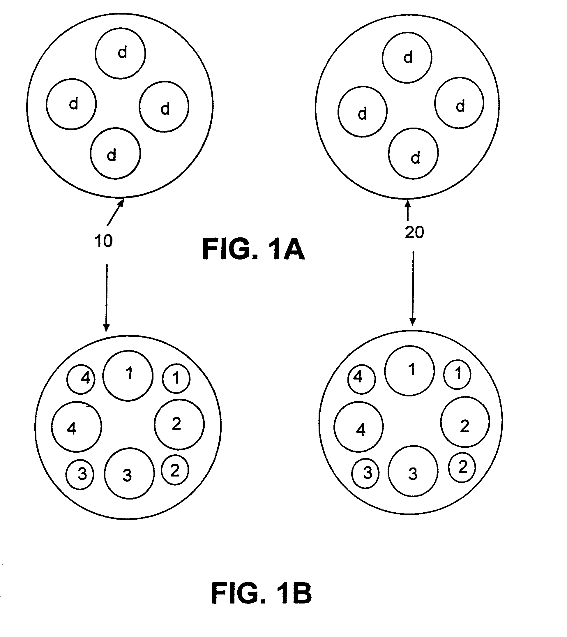
[0050] The following experiment is performed to profile the expression levels of both very rare and abundant transcripts in four different cellular states relative to a fifth reference state with an array-based hybridization assay using a single array.

[0051] A. Experimental Setup

[0052] Each of four samples contains a population of nucleic acids representing the transcript profile of the reference state and a population of nucleic acids representing the transcript profile of one of the four alternative states, such as cells grown under four different conditions, isolated from four different patients, or treated with four different drug candidates. The representatives from the reference state are labeled with one fluorophore and the representatives from each of the other states are labeled with a second different fluorophore. The samples are highly concentrated, each in 2 .mu.l of hybridization buffer solution containing 1.0 M NaCl, 10 mM Tris-HCl (pH 7.6), 0.005% Triton X-10...


PUM

PropertyMeasurementUnit
Pressureaaaaaaaaaa

Abstract

Methods are provided for depositing a quantity of fluid onto the surface of an array. In the subject methods, a thermal inkjet head loaded with the fluid is positioned in opposing relationship to, e.g. over, the array surface. Actuation of the thermal inkjet results in the expulsion of a quantity of fluid onto the array surface. The subject methods find particular use in array-based binding assays in which an array of binding agents is employed for the detection of an analyte(s), particularly array-based hybridization assays.

Description

[0001] 1. Technical Field[0002] The field of this invention is nucleic acid arrays.[0003] 2. Background of the Invention[0004] "Biochips" or arrays of binding agents, such as oligonucleotides and peptides, have become an increasingly important tool in the biotechnology industry and related fields. These binding agent arrays, in which a plurality of binding agents are deposited onto a solid support surface in the form of an array or pattern, find use in a variety of applications, including gene expression analysis, drug screening, nucleic acid sequencing, mutation analysis, and the like.[0005] In array-based assays in which an array of binding agents is employed, the array is typically contacted with a fluid sample that is suspected of containing the analyte(s) of interest. In currently employed protocols, contact of the array with the sample fluid is achieved in a number of different ways. Thus, a fluid sample may be contacted with the surface of the array using a pipette. In other ...

Claims


Application Information

Patent Timeline
IPC IPC(8): B01J19/00C40B40/06C40B40/10C40B60/14
CPCB01J19/0046B01J2219/00378B01J2219/00527B01J2219/00529B01J2219/00585B01J2219/0059B01J2219/00596B01J2219/00605B01J2219/00608B01J2219/00612B01J2219/00619B01J2219/00621B01J2219/00637B01J2219/00659B01J2219/00707B01J2219/00722B01J2219/00725B01J2219/0074C40B40/06C40B40/10C40B60/14
Inventor CAREN, MICHAEL P.LUEBKE, KEVIN J.
Owner AGILENT TECH INC
Why Eureka
Try Eureka