
Hook assembly used for waist-adjusing mechanism of garment and garment having waist-adjusting mechanism

a technology of adjusting mechanism and hook assembly, which is applied in the direction of hook fasteners, clothes making applications, protective garments, etc., can solve the problems of inability to adjust the waist size of pants or skirts, and inability to meet the needs of women's waist size adjustment,

Inactive Publication Date: 2001-09-27
KATO KOJI
View PDF0 Cites 4 Cited by
  • Summary
  • Abstract
  • Description
  • Claims
  • Application Information

AI Technical Summary

Benefits of technology

[0225] As described above, the pants 1 according to the seventh embodiment has the following advantageous effects.
[0226] If an external force is applied in such a direction as to enlarge the size of the waist belt 2 of the pants 1, the size of the waist belt 2 can be prolonged at the joined portion by the hook assembly 100 located at the upper ends of the front center opening 3. Specifically, the upper ends of the front center opening 3 can be joined by the hook assembly 100 in an adjusted state so as to fit to the waist size of the user who puts on the pants 1. Moreover, at the area from the upper part to a predetermined part downward of the outer cloth 3a (area where the adjusting cloth 21 is sewed between the outer cloth 3a and the fastener tape FA), the waist size of the pants 1 can be prolonged within an extendible length of the overlap 21a. Furthermore, since the buttonhole 31ax of the buttonhole piece 31 is the slot that has a component extending substantially in a horizontal direction, the outer cloth 3a can change its position to the inner cloth 3b, at which it is restricted from moving in the waist direction of the pants 1, in accordance with the position of the button thereof along the slot of the buttonhole 31ax. Therefore, the buttonhole piece 31 never restrict an extension of the waist size of the pants 1 within the fixed range where the button of the outer cloth 3a is movable.
[0227] The upper end of the fastener tape Fa is held and sewed inside the belt lining 2a while slanted outwardly of the edge of the outer cloth 3a as shown in FIG. 24 or sewed only on the adjusting cloth 21 up to the same height as the upper end of the adjusting cloth 21 as shown in FIG. 25. Therefore, the upper end of the fastener tape Fa and the portion of the fastener tape Fa stitched to the adjusting cloth 21 moves outwardly from the edge of the outer cloth 3a. Thus, a section where the waist size of the pants 1 is adjustable is completely continuous from the upper end of the pants 1 downward to the portion of the adjusting cloth 21. Therefore, it is possible to lessen more a tight feeling of the user when he or she puts on the pants 1 and decrease an influence on the appearance by a periphery of the front center opening 3 being pulled or wrinkled.
[0228] Specifically, if the size of the waist belt 2 of the pants 1 becomes long, the size of the portion around the waist becomes long accordingly. Consequently, it is impossible to get rid of the tight feeling if a room is provided only on the waist belt. With the pants 1 of the seventh embodiment, the waist belt 2 of each part of the pants 1 becomes long according not only to a change of the waist size of the user but also to a change of a size of a portion around the waist. Thus, the user has no tight feeling. Moreover, it also prevents the peripheral part of the front center opening 3 from being pulled or wrinkled, thereby improving the appearance thereof.
[0230] An eighth embodiment is described hereafter. FIG. 28 is an explanatory drawing showing one example of sewing a zip fastener and an adjusting cloth on a garment having a waist-adjusting mechanism according to an eighth embodiment of the invention. FIG. 29 is an explanatory drawing showing another example of sewing a zip fastener and the adjusting cloth on the garment having the waist-adjusting mechanism according to the eighth embodiment of the invention. FIG. 30 is a perspective view, enlarged in part, of the example of sewing the zip fastener and the adjusting cloth on the garment having the waist-adjusting mechanism according to the eighth

Problems solved by technology

Therefore, it is impossible to adjust the waist size of the pants or skirt.
However, these inventions have complicated mechanisms, so that the prices thereof cannot be low.
In addition, the dimension of the lower part of the waist belt may become short.
In this case, the portion around the front center part is pulled, thereby deteriorating the appearance.
On the other hand, if the lower part of the waist belt is given a room, the lower part becomes excessive when the waist size of the user becomes smaller, thereby generating wrinkles on the pants and affecting the appearance.

Method used


Image

  • Hook assembly used for waist-adjusing mechanism of garment and garment having waist-adjusting mechanism
  • Hook assembly used for waist-adjusing mechanism of garment and garment having waist-adjusting mechanism
  • Hook assembly used for waist-adjusing mechanism of garment and garment having waist-adjusting mechanism

Examples


second embodiment

[0177] SECOND EMBODIMENT

[0178] A second embodiment is describer hereafter. FIG. 15 is an exploded perspective view of a hook assembly according to a second embodiment of the invention.

[0179] In a hook assembly 100 according to the second embodiment, a hook attachment plate 103X of a hook element 100X has accommodating dents 103b at a jointed portion with the hook body 102 so as to accommodate the hook claws 102b, in contrast with the hook assembly of the first embodiment. Moreover, a socket attachment plate 105X of a socket element 100BX has accommodating dents 105b at a jointed portion with the socket body 104 so as to accommodate the socket claws 104c. The hook attachment plate 103X has through holes 103ax corresponding to the through holes 103a. Furthermore, the socket attachment plate 105X has through holes 105ax corresponding to the through holes 105a.

[0180] In addition, the socket attachment plate 105X has a bulged portion 105c configured by an X-shaped groove between those tw...

third embodiment

[0183] THIRD EMBODIMENT

[0184] A third embodiment is describer hereafter. FIG. 16 is an exploded perspective view of socket element 100BY of a hook assembly 100 according to a third embodiment of the invention.

[0185] In the third embodiment, a socket attachment plate 105Y of a socket element 100BY has accommodating dents 105by at a jointed portion with the socket body 104 so as to accommodate the socket claws 104c.

[0186] At the jointed portion of the socket attachment plate 105Y with the socket body 104, the accommodating dents 105by are provided only at an area where the socket claws 104c are housed. Thus, there is provided a room where connecting bridges 104b of the socket body 104 are fitted without interruption. The socket attachment plate 105Y has through holes 105ay corresponding to the through holes 105a.

[0187] In addition, the socket attachment plate 105Y has a bulged portion 105c configured by an X-shaped groove between those two accommodating dents 105b.

[0188] The hook asse...

fifth embodiment

[0194] FIFTH EMBODIMENT

[0195] A fifth embodiment is describer hereafter. FIG. 18 is an exploded perspective view of a hook assembly according to a fifth embodiment of the invention.

[0196] The fifth embodiment of hook assembly 100 can be structured to have the conventional hook element 200A and the first embodiment of socket element 100B. Specifically, the socket element 100B has the plural sockets 141, 142 formed at a fixed interval in the hooking direction so as to be caught by the hook 221 of the hook body 202.

[0197] With such structure, the hook element 200A can be easily assembled by inserting the bendable hook claws 202b in the through holes 203a of the hook attachment plate 203 and bending them thereafter. Similarly, the socket element 100B can be easily assembled by inserting the bendable socket claws 104b in the through holes 105a of the socket attachment plate 105 and bending them thereafter. Then, the hook element 200A is attached to one of the parted portions of the waist...


PUM


Abstract

A front center opening can be opened and closed by a zip fastener. A hook assembly joins upper ends of the front center opening in a separable way and adjusts a waist size of pants within a fixed range. An adjusting cloth is sewed between one of fastener tapes of the zip fastener and an outer cloth of the front center opening. The adjusting cloth has an overlap to provide an extra length on the waist size of the pants. The hook assembly adjusts the waist size of the pants so as to fit a waist size of a user. The overlap of the adjusting cloth is extended in a specified manner so as to adjust a size of the pants corresponding to a portion lower than the waist of the user.

Description

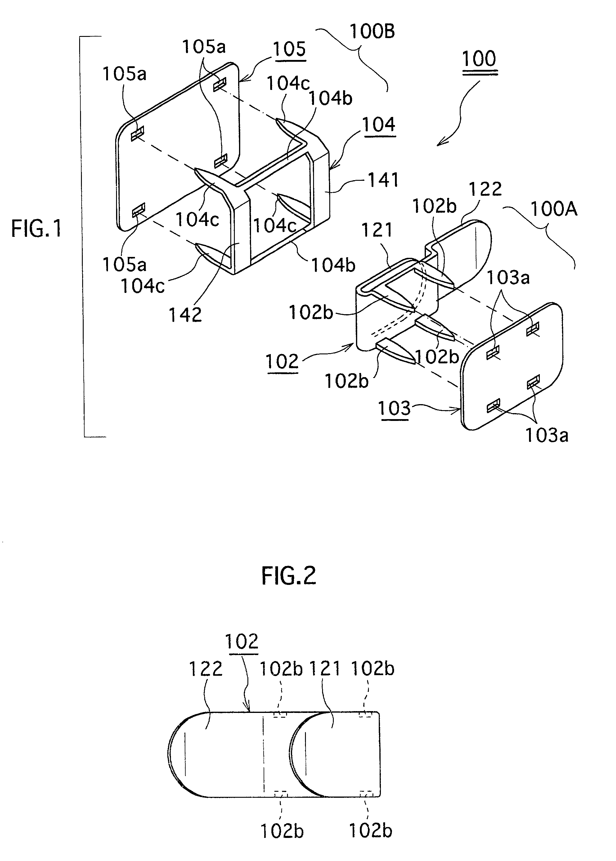
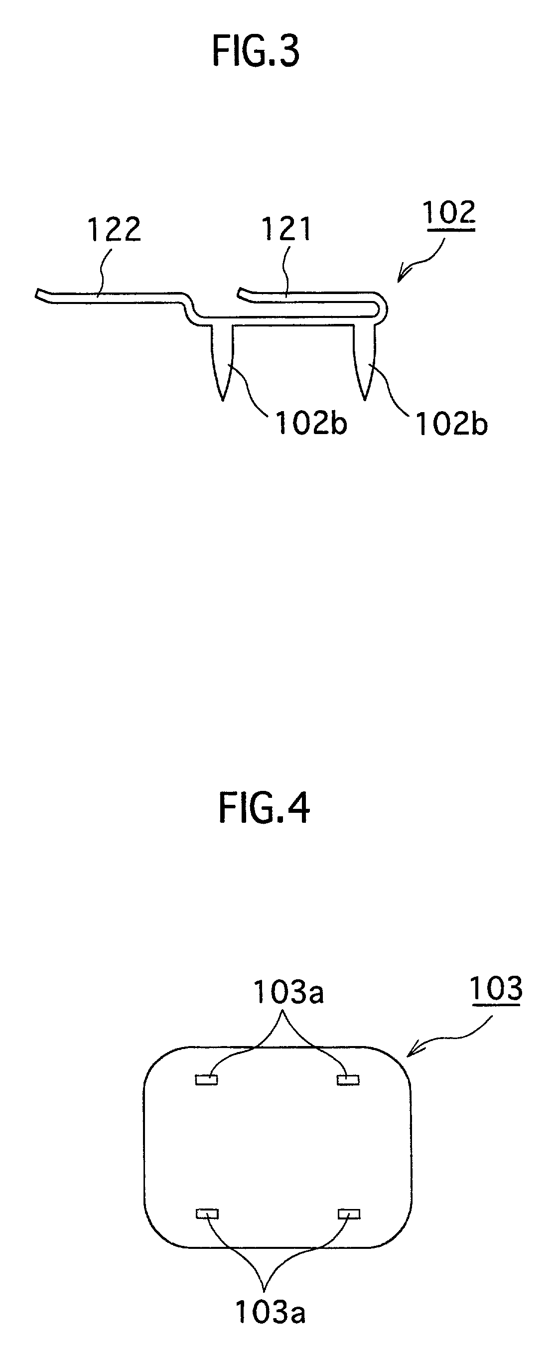
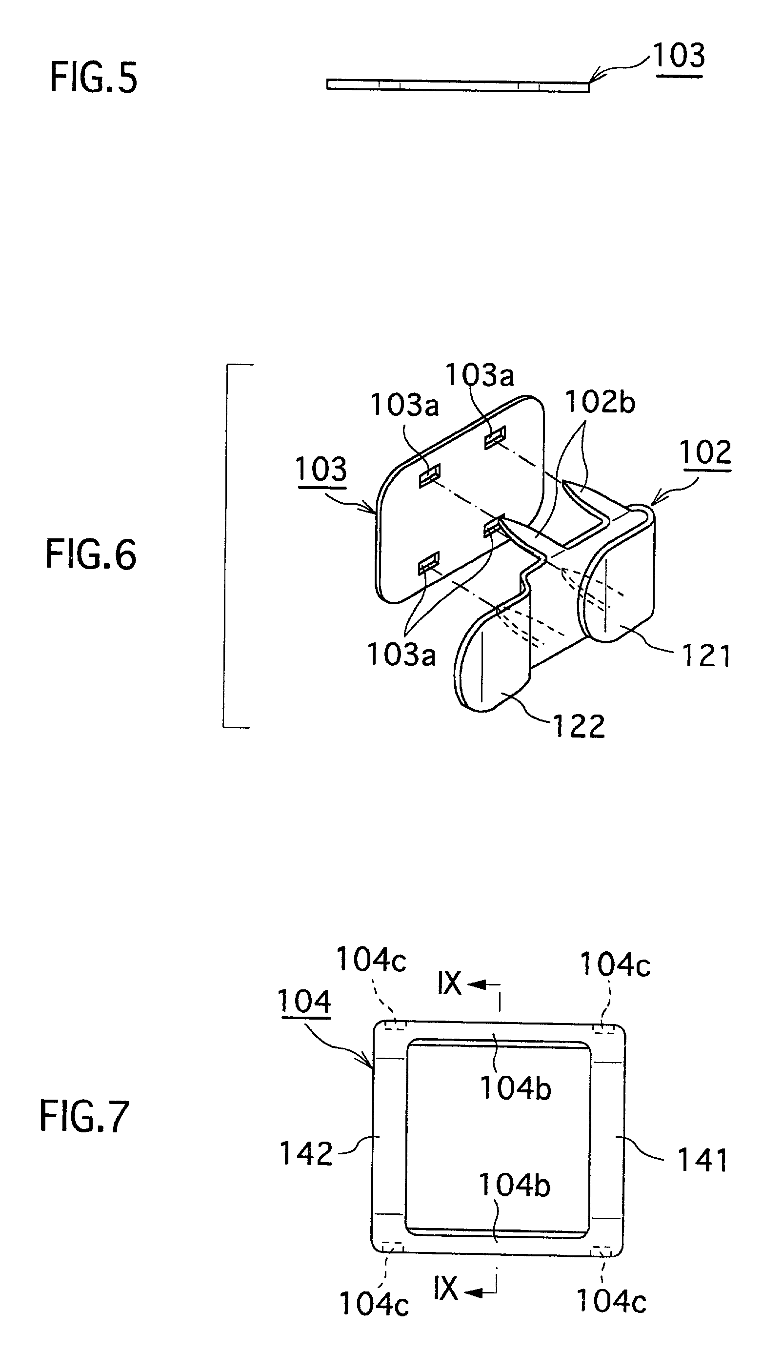
[0001] 1. Field of the Invention[0002] This invention relates to a hook assembly for a garment that joins a parted portions of a waist of a garment such as pants and a skirt, a decorative hook assembly that joins a portion of a decorative belt or a decorative cover, and a garment having a waist-adjusting mechanism composed of a fastener such as those hook assemblies attached thereto. Particularly, the invention relates to a garment having a waist-adjusting mechanism that can be adjusted to a waist size of a user such as pants having a waist-adjusting mechanism or a skirt having a waist-adjusting mechanism.[0003] 2. Description of the Related Art[0004] Generally, the pants or skirt have a waist parted so as to be opened thereat. Commonly, the parted portions are joined by a hook assembly 200 shown in FIG. 75.[0005] FIG. 75 is an exploded perspective view showing a conventional hook assembly.[0006] Referring to FIG. 75, the hook assembly 200 has a hook element 200A and a socket 241. T...

Claims


Application Information

Patent Timeline
IPC IPC(8): A41D1/14A41F9/02A44B13/00A41D1/06
CPCA41F9/025A41H37/06A44B13/0017A44B13/0041Y10T24/45241A44B13/00
Inventor KATO, KOJI
Owner KATO KOJI
Learn More