Locker

a technology of locking device and lock rod, which is applied in the field of locking device, can solve the problems of steel locking device, disadvantageous heavyness and high manufacturing cost, and lock device is not suitable for outdoor use,

Inactive Publication Date: 2001-11-22
CKI LOCKER LLC
View PDF0 Cites 6 Cited by
  • Summary
  • Abstract
  • Description
  • Claims
  • Application Information

AI Technical Summary

Benefits of technology

0009] In accordance with a particularly preferred form of the present invention, there is provided a locker. The locker comprises a first side wall having an interlocking portion, a second side wall having a first interlocking portion engaging the interlocking ...

Problems solved by technology

Such lockers, however, are not suitable for outdoor use because their steel construction deteriorates rapidly in such conditions.
Such steel lockers are, furthermore, disadvantageously heavy and expensive to fabricate.
Front-mounted locking mechanisms are disadvantageous because they may be vandalized by prying.
In addition, a channel-mounted coin receptacle is disadvantageously small and, thus, will overflow unless emptied regularly.
The time and skill required to weld a locker together is another disadvantage of a conventional locker.
Another common problem with known lockers is that they often become soiled by way of spills that occur therein, by foods that melt and stick to the compartment or by other means.
Such soiling often prevents a loc...

Method used


Image

  • Locker
  • Locker
  • Locker

Examples


Embodiment Construction

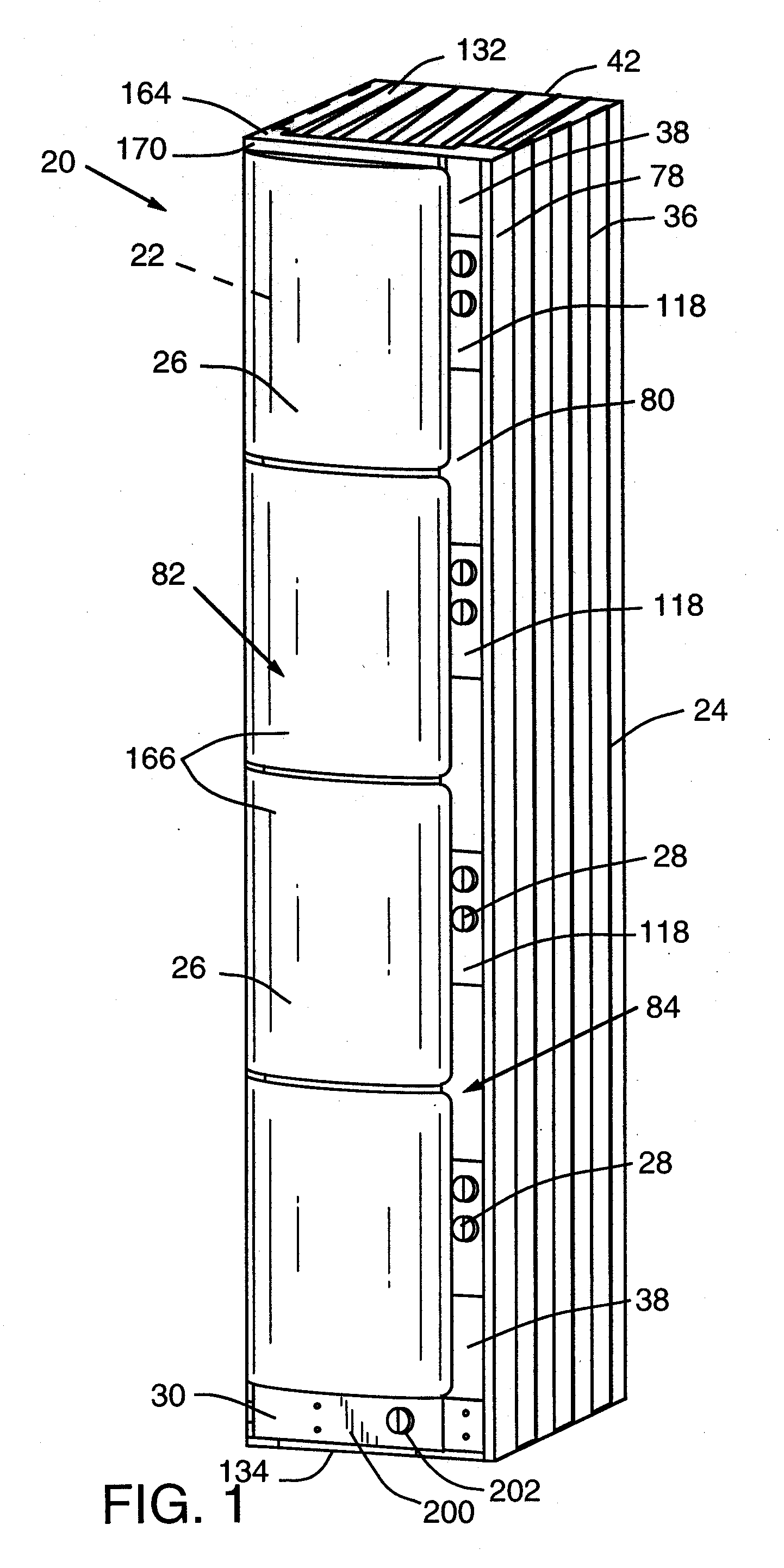
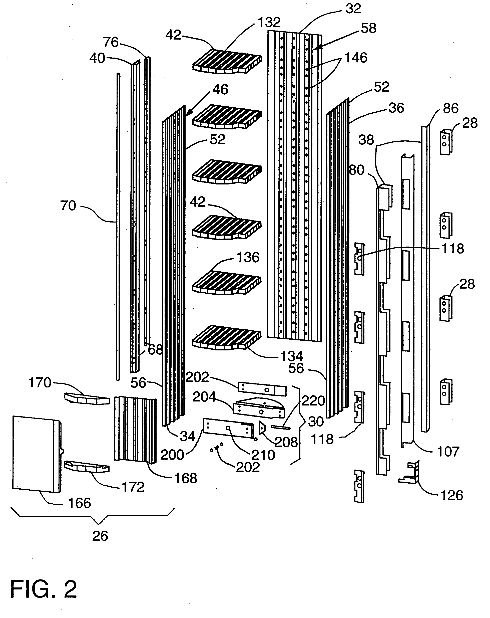
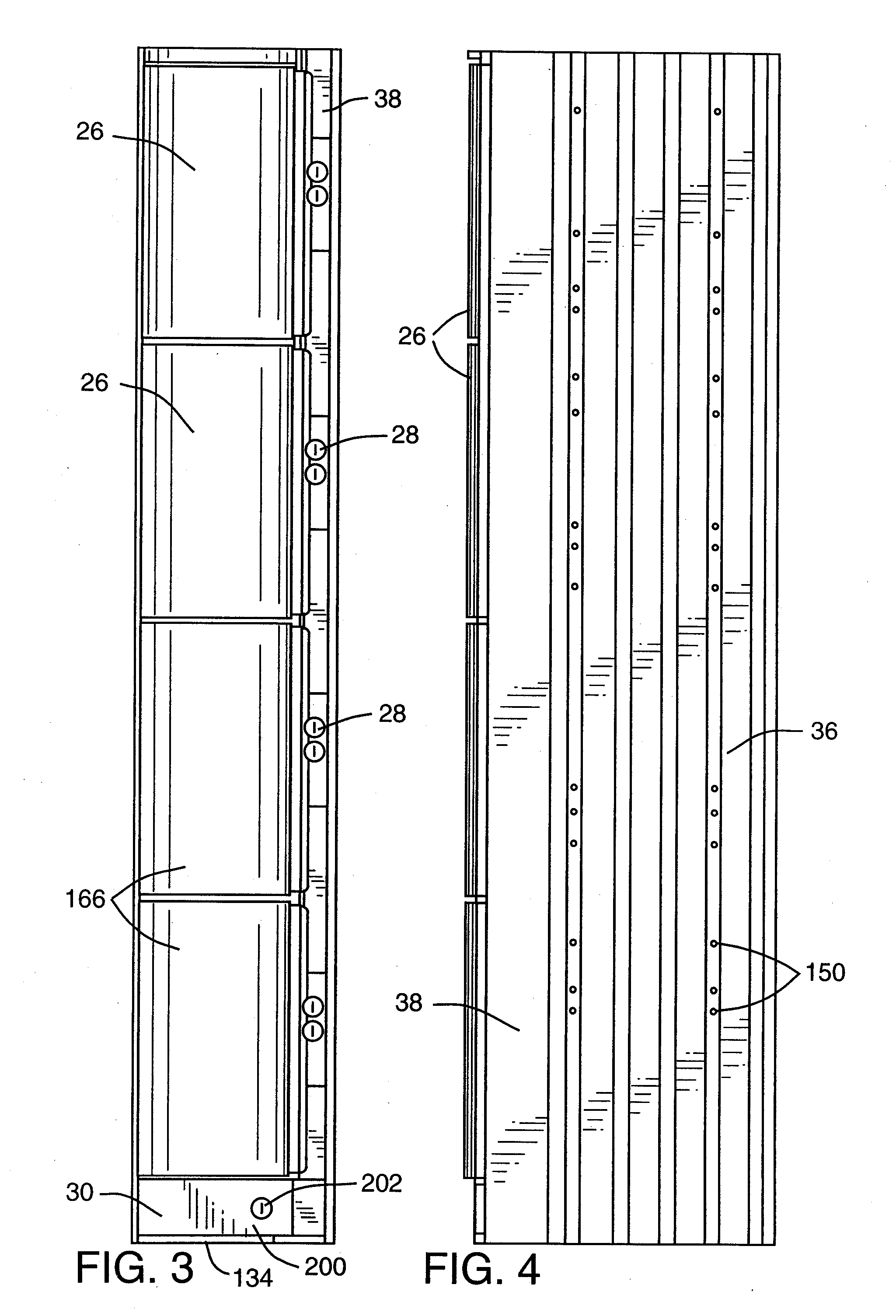
[0073] It is to be understood that the Figures and descriptions of the present invention included herein illustrate and describe elements that are of particular relevance to the present invention, while eliminating, for purposes of clarity, other elements found in a typical locker. Because the construction and implementation of such other elements are well known in the art, and because a discussion of them would not materially facilitate a better understanding of the present invention, discussion of those elements is not provided herein. It is also to be understood that the embodiments of the present invention that are described herein are illustrative only and are not exhaustive of the manners of embodying the present invention. For example, it will be recognized by those skilled in the art that the positions of the frame components including, for example, the hinge channel 40 and the lock channel 38, may be reversed if an alternate embodiment is preferred.

[0074] Referring now to t...


PUM


Abstract

<heading lvl="0">Abstract of Disclosure</heading> A locker. The locker comprises a first side wall having an interlocking portion, a second side wall having a first interlocking portion engaging the interlocking portion of the first side wall and a second interlocking portion, and a third side wall having an interlocking portion engaging the second interlocking portion of the second side wall. A coin receptacle, coin receptacle locking mechanism, a shelf and a door for the locker are also disclosed. A method of manufacturing a locker is also provided. The method comprises cutting a first wall from a first material to a desired length, cutting a second wall from the first material to the desired length, cutting a third wall to the desired length, and slidingly engaging the first, second and third walls. A method for limiting access to a locking mechanism is also provided, which comprises positioning the locking mechanism adjacent an inward facing surface and fastening the locking mechanism to the locker.

Description

Cross Reference to Related Applications[0001] Not ApplicableBackground of Invention[0003] Field of the Invention[0004] The present invention relates to lockers and, more particularly, to weather resistant coin operated lockers.[0005] Description of the Invention Background[0006] A variety of different methods and apparatuses have been developed for securing personal possessions in public areas. One apparatus that has been developed is a coin operated locker for storage of personal possessions. Such a locker commonly includes two vertical parallel side panels, a vertical rear panel attached to both side panels, a top and a bottom, thereby creating a storage compartment enclosed on five sides. The front of the locker typically has at least one lockable door. A front-mounted coin operated locking mechanism and a coin receptacle located beneath the locking mechanism in a channel are also common components of such lockers. The walls and door of lockers are typically fabricated from flat ...

Claims


Application Information

Patent Timeline
IPC IPC(8): E05G1/08G07F9/06G07F17/12
CPCE05G1/08G07F9/06G07F17/12
Inventor JERMAIN , RICHARD B.
Owner CKI LOCKER LLC
Why Eureka
Try Eureka