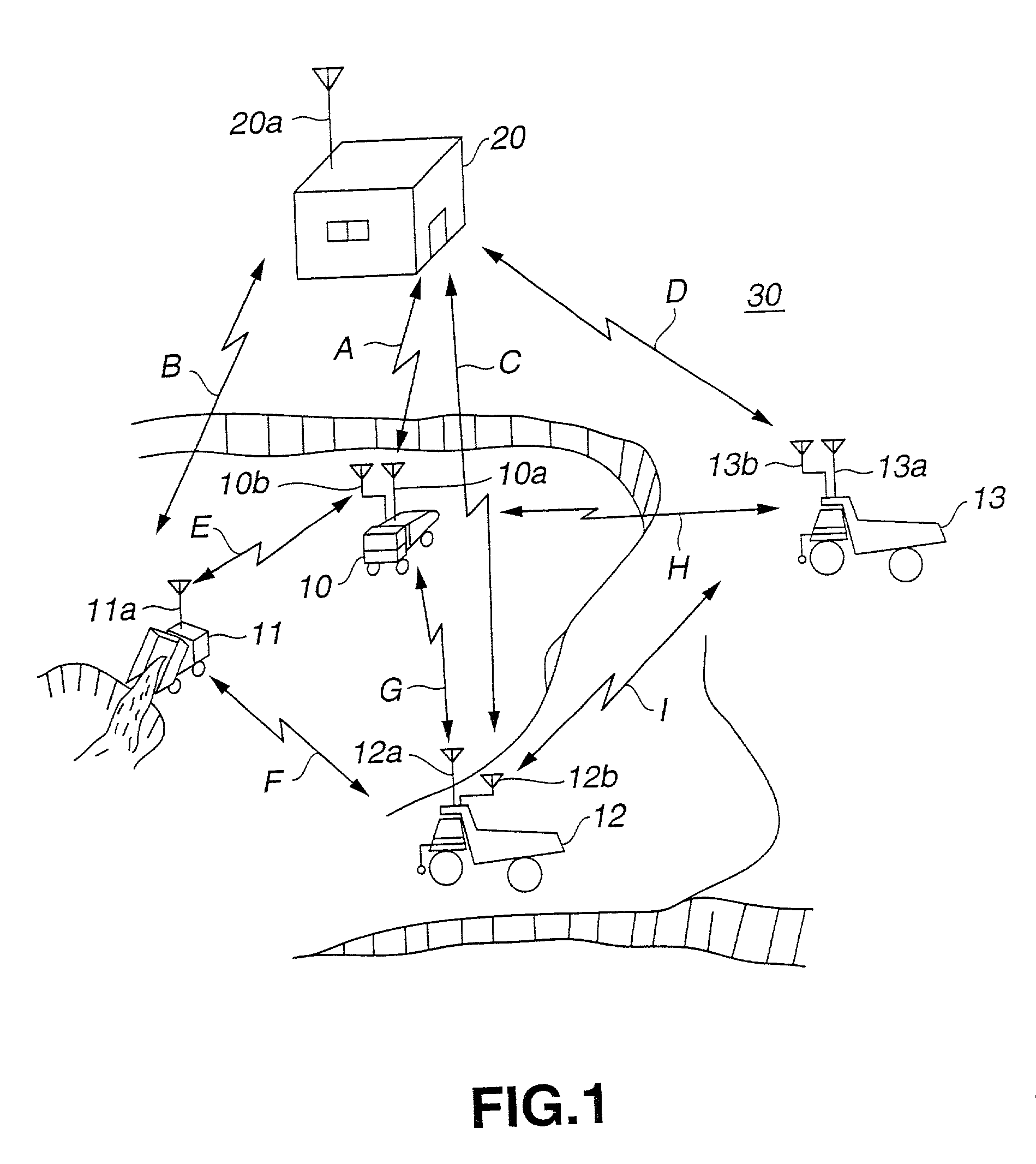
However, the use of a stationary installation entails numerous initial outlays associated with construction of the installation.
Further, it is difficult to adapt such a
system to a mine, where travel routes change frequently.
While it is possible to embed lane change sensors along the course of an
asphalt highway, this approach is not feasible for mine roads, which are maintained by graders.
Even if lane change sensors were embedded in an
asphalt travel path (roadway), the
asphalt road would not be able to bear the weight of the vehicle.
Also, lane change sensors embedded in the roadway would be crushed by the weight of the vehicle.
Assuming that lane change sensors were embedded in road paved with gravel or the like, the need to periodically maintain the pavement through grading poses the problem of equipment, such as lane change sensors, embedded in the pavement being crushed during the grading operation.
Further, lane change sensors can detect a vehicle only after it has entered a lane; while this presents no particular problem in the case of highways and other roadways with minimal cross-traffic, in mining operations, which typically have a complex web of routes, there exists a risk, depending on the condition of travel of a vehicle, that the vehicle will be detected only as it approaches an intersection.
This means that where the risk exists that traveling vehicles will interfere (collide) in proximity to an intersection, the
delay in control to prevent collision may result in collision of the vehicles.
The
system disclosed in
Citation 4 assumes travel of manned vehicles over a predetermined course (prearranged travel
route) in a manner analogous to unmanned vehicles, with
monitoring and control being performed from a central monitoring
station, and as such is difficult to implement in situations where the
human operator of a vehicle may choose, for example, to make a U-turn mid-course or otherwise change course from time to time.
Further, manned vehicles are driven by human operators, and some operators may find disagreeable the approach of travel to a predetermined destination selected in accordance with the operation.
Forcible introduction of a
system that ignores operator preference will have a negative
impact on operations.
However, depending on communication conditions, it may occur that an unmanned vehicle cannot receive vehicle position data from a manned vehicle; in such instances, there exists the risk of a
delay in the determination process for interference between vehicles, resulting in an inability exercise proper control to prevent interference between vehicles.
For manned vehicles, in instances of interference between vehicles, while a Reduce Speed command sent from the unmanned vehicle is displayed on the display screen of a
display device, it is not possible to ascertain the positional relationship vis--vis the other vehicle.
This is not possible with the system disclosed in
Citation 5, however.
There are also various costs associated with equipping vehicles that do not enter the mine, such as repair vehicles, with position-measuring devices and communication devices.
Position-measuring devices and communication devices that are used infrequently have increased likelihood of malfunction when it is attempted to operate the device.
While it is possible to design position-measuring devices and communication devices to be readily attachable and detachable, in some instances there may be an insufficient number of devices.
From the standpoint of preventing vehicle interference, that is, for reasons of
vehicle safety, vehicles lacking position-measuring devices and communication devices due to malfunction or a shortage thereof cannot be employed.
This means that despite the availability of vehicles to do the work, the vehicle resources cannot be used effectively.
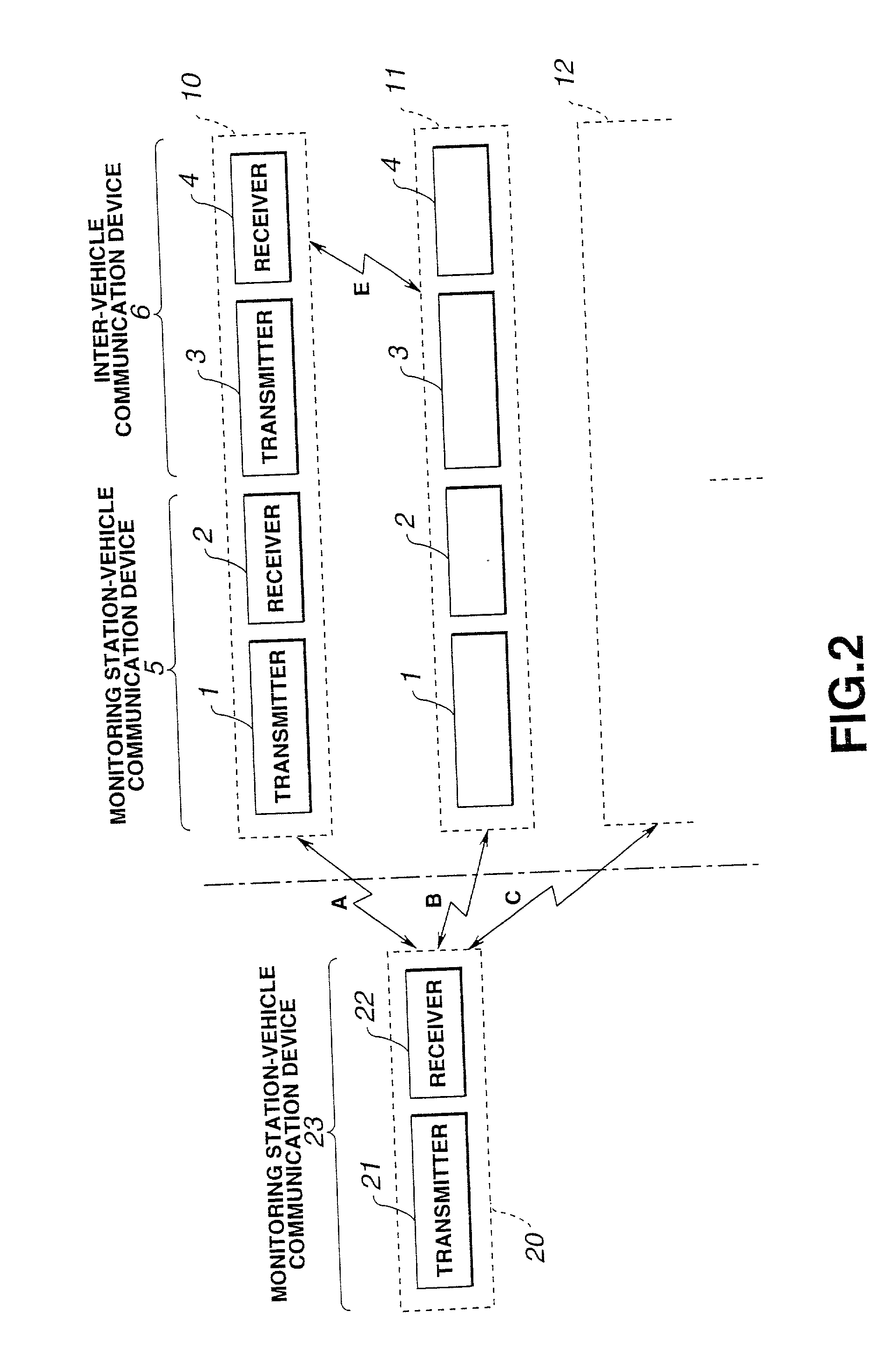
In the vehicle monitoring systems of the Citations cited above, the radio
waves used for communications of the short-range (e.g. SS transmission) communication devices used for communication among vehicles can only travel over short distances (from 100 m to 1 km), and in large-scale mining operations involving large distances between vehicles and large numbers of vehicles (50 to 100, for example), it is not possible for all vehicles to know the current positions of other vehicles.
With the conventional vehicle monitoring systems described above, while long-range (10 km to 20 km) communications are possible if long-range (e.g. VHF) communication devices are used, slow transmission speed (9600 bps) creates the problem of inability to constantly be apprised of the current locations of a multitude of vehicles.
Since large amounts of data are transmitted to the monitoring station from the multitude of vehicles, the volume of data being transmitted is quite large.
Since the communications format entails slow transmission speeds, the communications circuit becomes complicated and the communications circuit becomes overloaded, resulting in inability in
actual practice to manage and monitor vehicles.
Where it is attempted to address this problem by employing short-range communication devices capable of higher transmission speeds (256 kbps) for communication among vehicles, while it becomes possible to transmit very large amounts of data rapidly, the limited range of the radio
waves makes it impossible to provide full communications coverage over the entirety of large
work site.
Thus, of the vehicles spread over entirety of a large
work site, it will not be possible for a vehicle to communicate with another vehicle located a distance away that exceeds the short range transmission range (100 m to 1 km, for example), and hence there will be no way to determine the current position of this other vehicle.
Accordingly, in large-scale mining operations involving large distances between vehicles and large numbers of vehicles, it has not been possible for all vehicles lo be constantly apprised of the current locations of other vehicles.
When using the circle computation of Method 1, there exists a risk that the estimated future range of possible locations for the other vehicle may interfere with the own vehicle if the distance between the two vehicles has been shortened by passing by each other, for example.
To describe the processes described in FIGS. 14 and 15 in other terms, where the range of possible locations for an own vehicle and the range of possible locations for another vehicle interfere, and the other vehicle is traveling in the same direction on the arranged
route of the own vehicle, there exists a risk that the own vehicle will overtake the other vehicle.
Where the range of possible locations of the other vehicle interferes with the range of possible locations of the own vehicle, and the other vehicle is not traveling in the same direction on an arranged route, there exists a risk of collision between the vehicles.
If by some fluke both UHF communication and SS communication should be disabled (inter-vehicle communication devices experience malfunction, the range of possible locations for the other vehicle will continue to expand so that the range of possible locations for the other vehicle interferes with the range of possible locations for the own vehicle.


