Identifying one of a plurality of wires of a power transmission cable

Inactive Publication Date: 2002-03-07
AMBIENT CORPORATION
View PDF0 Cites 99 Cited by
  • Summary
  • Abstract
  • Description
  • Claims
  • Application Information

AI Technical Summary

Problems solved by technology

If data is present on the medium voltage power grid, it would be desirable to couple broadband data streams from transformer substations to entire sections of a neighborhood, but the distribution transformers effectively block high frequency energy and thus block the data from getting to the LV drop lines.
For such a small number of potential users, it is not econo

Method used


Image

  • Identifying one of a plurality of wires of a power transmission cable
  • Identifying one of a plurality of wires of a power transmission cable
  • Identifying one of a plurality of wires of a power transmission cable

Examples


Example

[0046] Overhead and underground medium voltage transmission lines may be used for the bi-directional transmission of digital data. Such transmission lines cover the path between a power company's transformer substation and one or more MV-LV distribution transformers placed throughout a neighborhood. The MV-LV distribution transformers step the medium voltage power down to low voltage, which is then fed to homes and businesses.

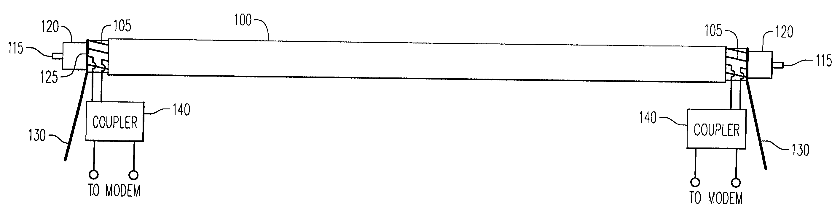
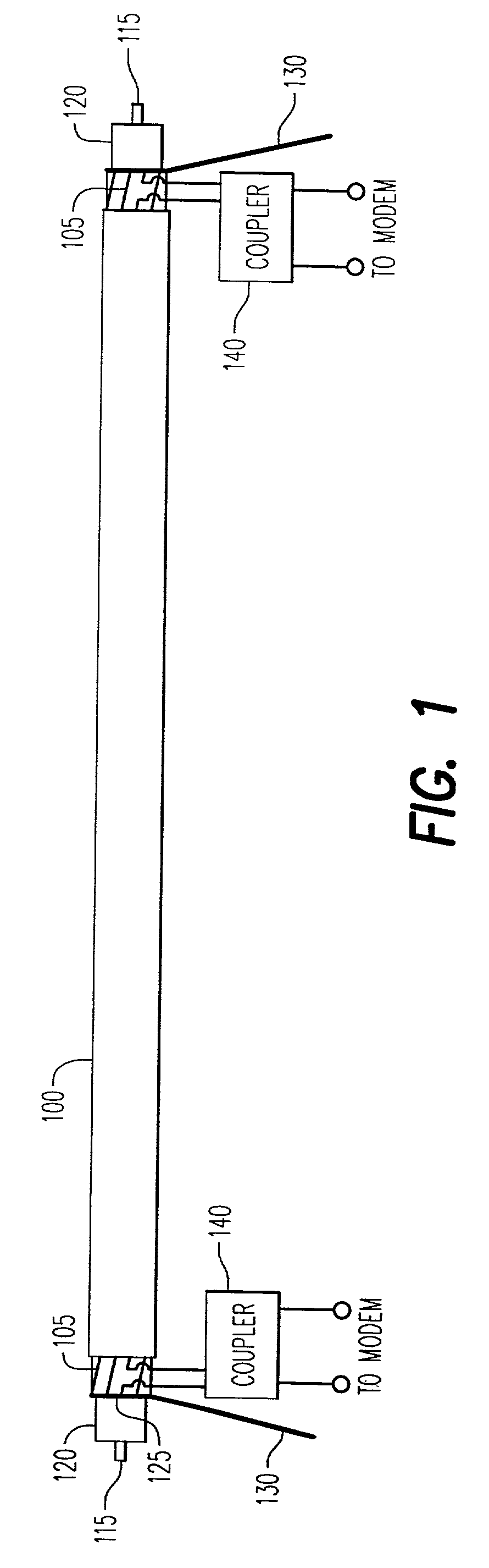
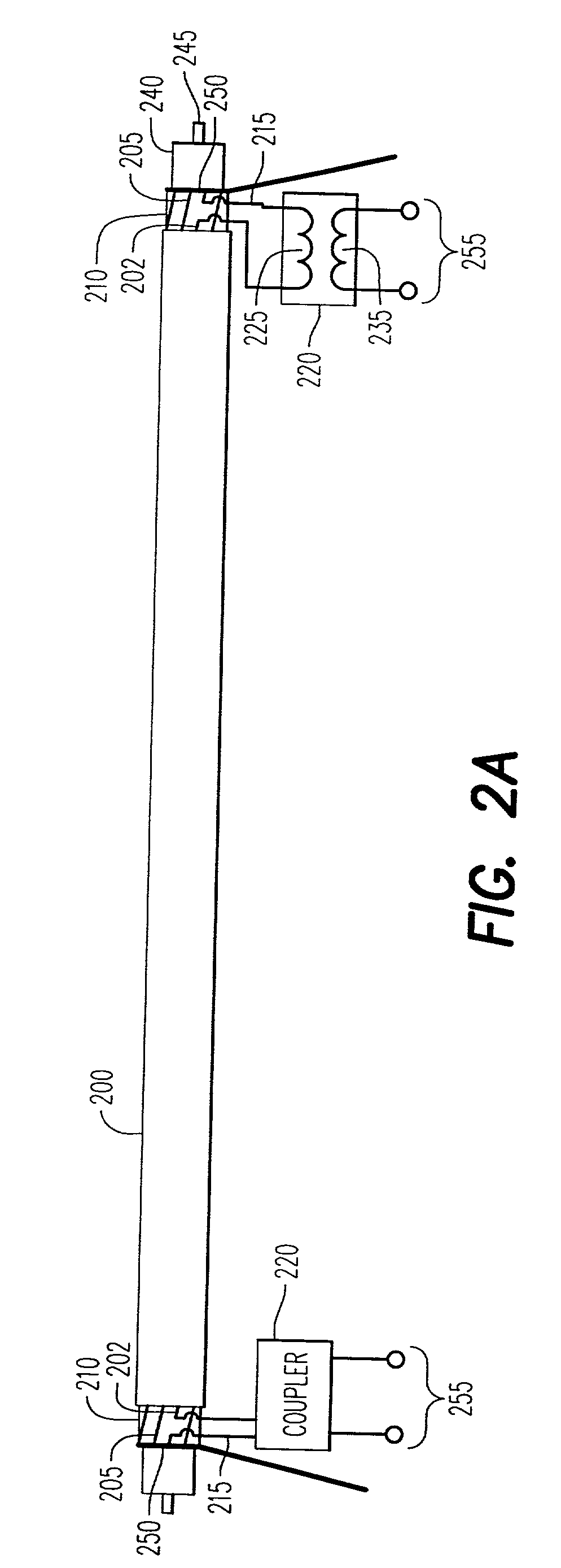
[0047] The present invention relates to a use of a coupler in a medium voltage grid. The coupler is for enabling communication of a data signal via a power transmission cable. It has a first winding for coupling the data signal via a conductor of the power transmission cable, and a second winding, inductively coupled to the first winding, for coupling the data signal via a data port.

[0048] One embodiment of the present invention is employed with a power transmission cable having one or more neutral wires, i.e., conductors, wrapped around an outer layer of the c...


PUM


Abstract

There is provided an apparatus for enabling communication of a data signal via a power transmission cable. The apparatus comprises (a) a first winding for coupling the data signal via a conductor of the power transmission cable, and (b) a second winding, inductively coupled to the first winding, for coupling the data signal via a data port.

Description

[0001] The present application is claiming priority of U.S. Provisional Patent Application Serial No. 60 / 173,808, filed on Dec. 30, 1999, and Serial No. 60 / 198,671, filed on Apr. 20, 2000.[0002] 1. Field of the Invention[0003] The present invention relates to communication of a data signal over a power distribution system, and more particularly, to a use of an inductive coupler for coupling a data signal via a conductor in a power transmission cable.[0004] 2. Description of the Prior Art[0005] Low voltage (LV) power lines within the confines of a home or business have been used as a medium for point to point or network communications using so called "carrier" systems in which a data signal is modulated onto a high frequency (HF) carrier and transmitted over the power lines. Internet access, which requires "last mile" connectivity between the Internet data trunk and each domicile, would greatly enhance the utility of such networks.[0006] A medium voltage (MV) typically 4-66 kV is red...

Claims


Application Information

Patent Timeline
IPC IPC(8): H04B3/56H04B3/54
CPCH04B3/56H04B2203/5487H04B3/54G01R19/00H04B1/00
Inventor CERN, YEHUDAKAPLUN, GEORGE
Owner AMBIENT CORPORATION
Why Eureka
Try Eureka