Magnetic separator

a magnetic separator and magnetic separator technology, applied in the direction of solid separation, transportation and packaging, chemistry apparatus and processes, etc., can solve the problems of rotor itself, damage or destruction of magnets, and waste of resources, and the purification of waste materials by water and/or heavy media plants,

Inactive Publication Date: 2002-03-14
HOWELL BILLY R
View PDF0 Cites 11 Cited by
  • Summary
  • Abstract
  • Description
  • Claims
  • Application Information

AI Technical Summary

Benefits of technology

[0012] The present invention in its several disclosed embodiments alleviates the drawbacks described above with respect to the separation of non-ferrous metal material from ferrous metals, rocks, glass, wood, rubber, dirt and other such debris by means of any eddy current which incorporates several beneficial features. An eddy current separator apparatus is disclosed whereby electrically conductive metals are separated from other materials such as glass, rubber, wood, rocks and dirt in a novel and unique manner. The present invention separates non-ferrous metals from the debris by a shredding process through the utilization of a single magnetic rotor. The effect of the magnetic rotor is to upwardly lift or boost the non-ferrous metals as they travel upon a continuous belt. The lifting boost of the rotor, together with the lateral inertia induced by the moving belt applies a resultant force upon the non-ferrous metals that "throws" the affected metals further beyond the end of the belt than the remainder of the debris.

Problems solved by technology

In at least one past instance, residue was purified by water and / or heavy media plants which proved to be costly.
The presence of the iron creates resistance resulting in heat, thereby burning through the fiberglass belt drum and sometimes damaging or destroying the magnets, and possibly the rotor itself.
This damage is due to the tight tolerances at which the two rotating components are run with respect to one another.

Method used


Image

  • Magnetic separator
  • Magnetic separator
  • Magnetic separator

Examples


Embodiment Construction

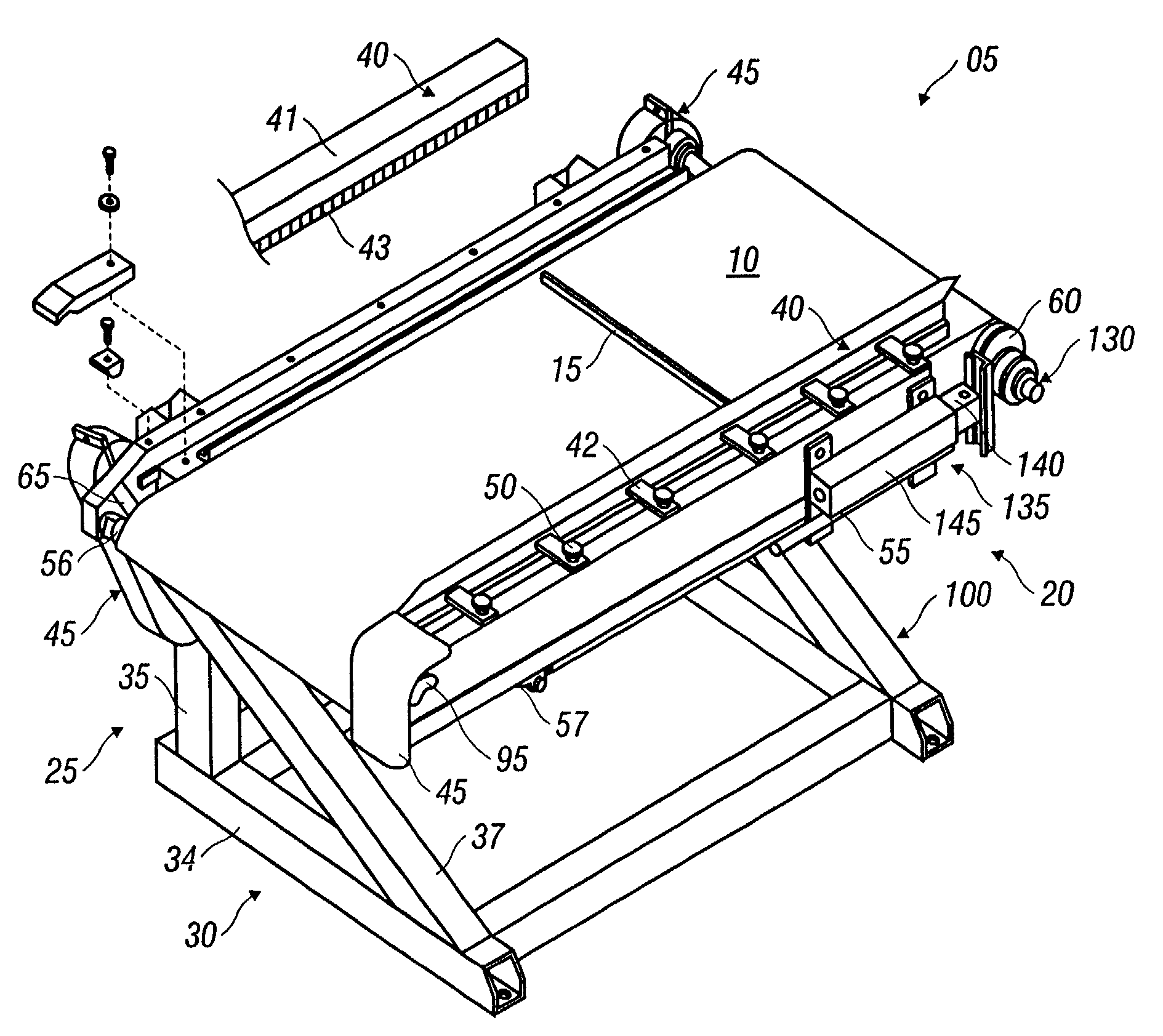
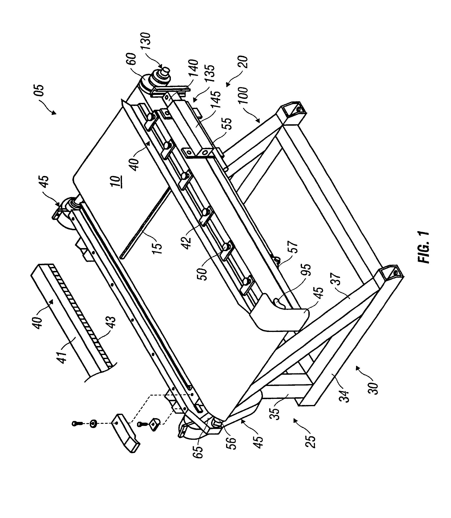
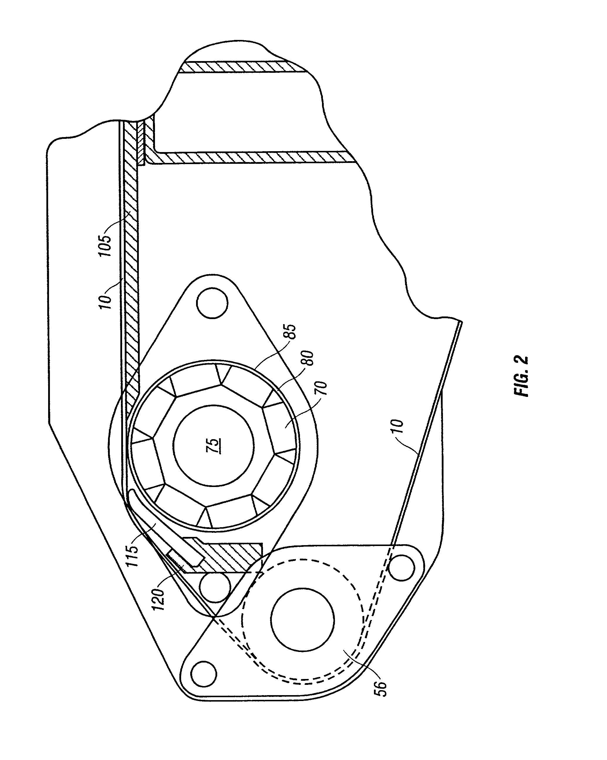
[0042] As required, detailed embodiments of the present invention are disclosed herein; however, it is to be understood that the disclosed embodiments are merely exemplary of the invention that may be embodied in various and alternative forms. The figures are not necessarily to scale, some features may be exaggerated or minimized to show details of particular components. Therefore, specific structural and functional details disclosed herein are not to be interpreted as limiting, but merely as a basis for the claims and as a representative basis for teaching one skilled in the art to variously employ the present invention.

[0043] Furthermore, elements may be recited as being "coupled"; this terminology's use contemplates elements being connected together in such a way that there may be other components interstitially located between the specified elements, and that the elements so specified may be connected in fixed or movable relation one to the other.

[0044] Referring to the Figures,...


PUM


Abstract

An eddy current separator apparatus for separating non-ferrous metals from other materials. The apparatus includes a support frame and a table cantileverly suspended from the frame. An expansion and contraction mechanism is incorporated that is adapted to accept a continuous conveyor belt thereabout. The expansion and contraction mechanism is capable of being configured between an operating configuration and maintenance configuration. A continuous conveyor belt is constructed to be able to be looped about the expansion and contraction mechanism and the table such that the conveyor belt is drawn tight in the operating configuration and slackened in the maintenance configuration. In this manner, the continuous conveyor belt is easily removable from, and installable onto the table in the maintenance configuration. A magnetic rotor is positioned proximate a first side of the continuous conveyor belt and is adapted to generate an eddy current on an opposite second side of the continuous conveyor belt upon rotation for inducing an elevating force in non-ferrous metals for separation from other materials.

Description

RELATED PATENT APPLICATIONS[0001] This patent application is a continuation in part of U.S. patent application Ser. No. 09 / 169,014 filed on Oct. 8, 1998 entitled MAGNETIC SEPARATOR which claims the benefit of United States Provisional Application No. 60 / 061,624 filed Oct. 9, 1997 entitled MAGNETIC SEPARATOR. By this reference, the full disclosures including the drawings of U.S. Provisional Patent Application No. 60 / 061,624 and U.S. patent application Ser. No. 09 / 169,014 are expressly incorporated herein.[0002] This invention relates generally to metal separators. More specifically, but not by way of limitation, the invention is directed to an apparatus for separating non-ferrous metal material from ferrous metals, rocks, glass, wood, rubber, dirt and other such debris by means of an eddy current.DESCRIPTIONBackground Art[0003] In this present era of recycling and limited land-fill space, the necessity to reclaim reusable materials from debris and waste has become an utmost concern o...

Claims


Application Information

Patent Timeline
Patent Type & Authority Applications(United States)
IPC IPC(8): B03C1/247
CPCB03C1/247B65G21/06
Inventor HOWELL, BILLY R.
Owner HOWELL BILLY R
Why Eureka
Try Eureka