Al technical title is built by PatSnap Al team. It summarizes the technical point description of the patent document.
a trap and rock technology, applied in the field of rock simulating pest traps, can solve the problems of large outer housings, undesirable placement of traps in residences and businesses, and large number of homeowners
Inactive Publication Date: 2002-04-18
TOWNSEND LYLE
View PDF7 Cites 60 Cited by
Summary
Abstract
Description
Claims
Application Information
AI Technical Summary
This helps you quickly interpret patents by identifying the three key elements:
Problems solved by technology
Method used
Benefits of technology
0013] In both embodiments, an optional stake and hold-down chain may be provided which are used to secure the outer housing on the ground to prevent its movement.
Problems solved by technology
Because deadly diseases and filthy conditions are often associated with insects and rodents, the placement of traps inside residences and businesses where they may be in plain view of guests or visitors is undesirable.
One drawback of such traps is that the outer housings are relatively large structures that are visible at a distance.
Because of the negative connotation associated with insect and rodent traps, most homeowners find the visibility of such traps objectionable.
Although the traps may be placed behind other objects or covered with dirt to hide them, this is undesirable because it prevents the trapper from easily checking or retrieving the traps.
Method used
Image
Click on the blue label to locate the original text in one second.
Reading with bidirectional positioning of images and text.
Examples
Embodiment Construction
)
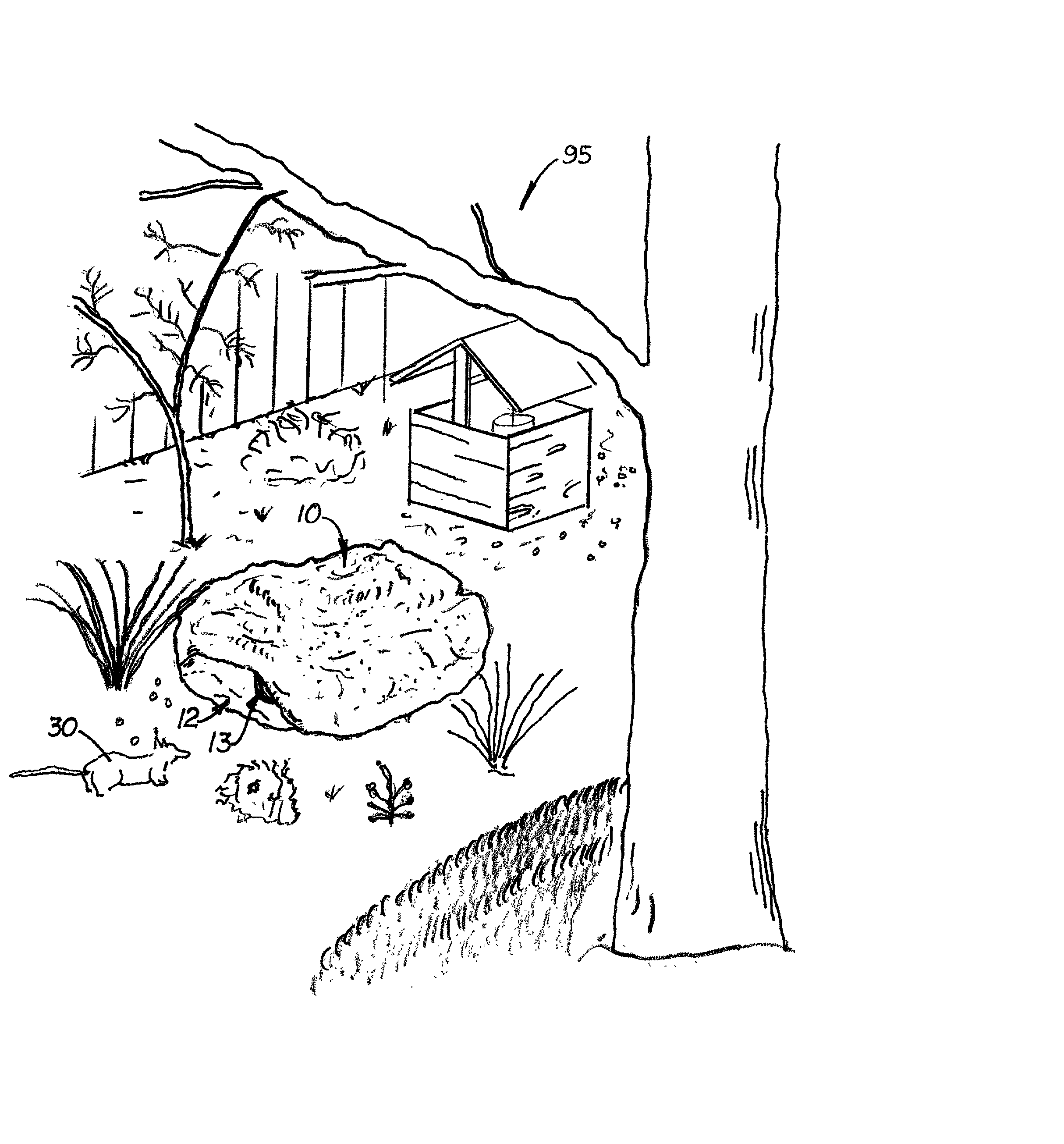
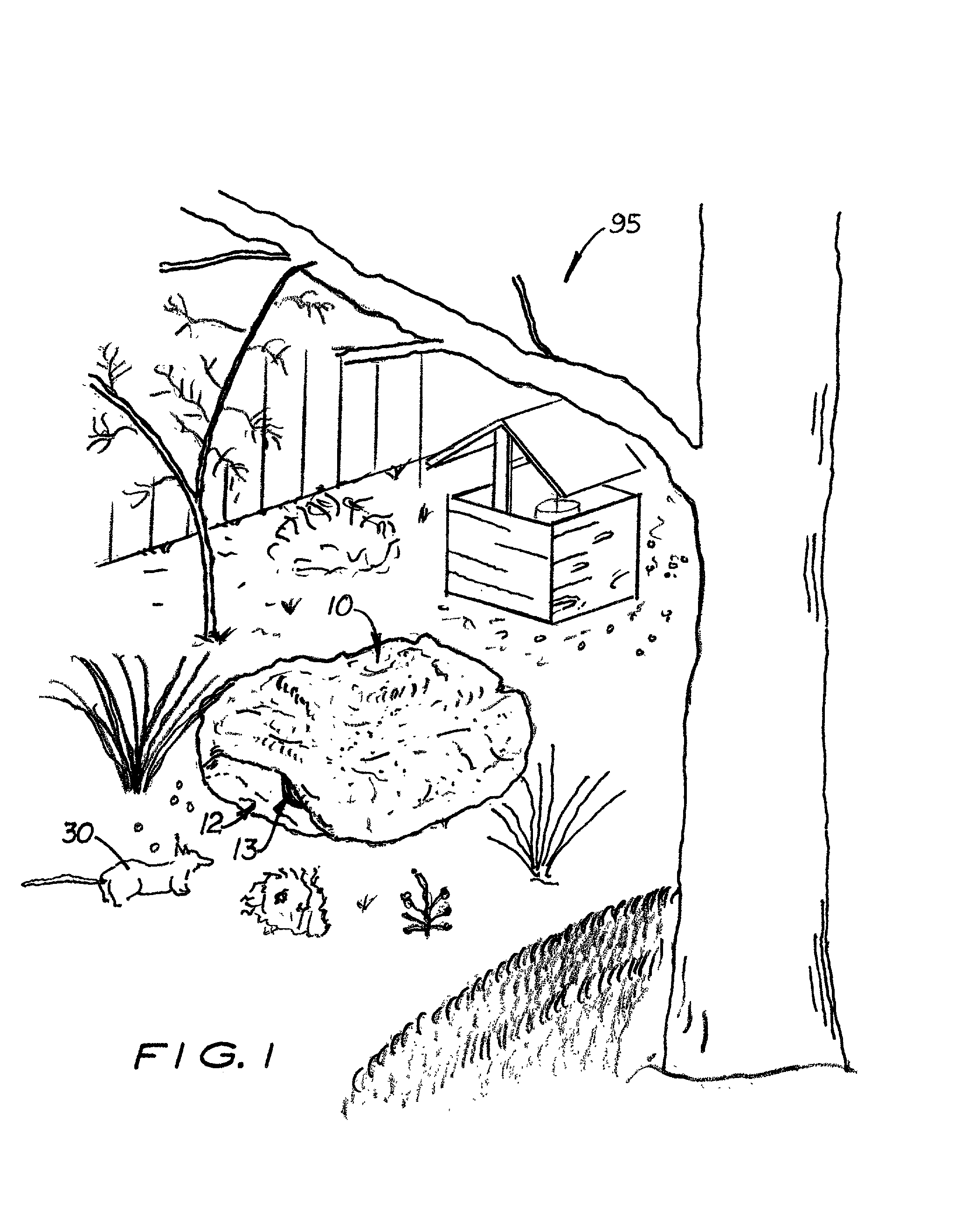
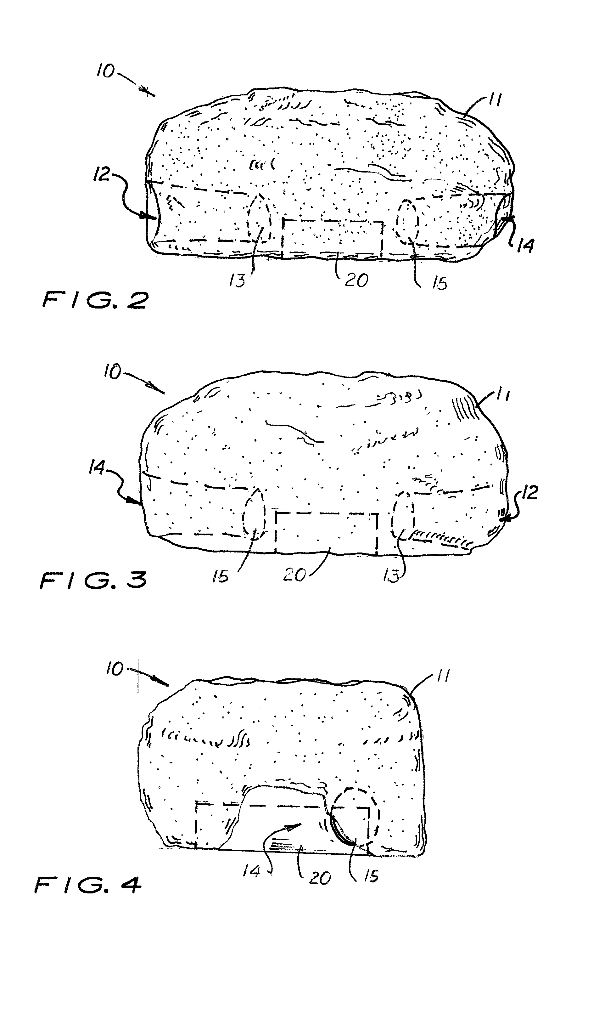
[0025] Referring to FIG. 1-5, there is shown and described a pest trap 10 designed to simulate a rock in a garden or landscape area 95. The pest trap 10 includes a hollow outer housing 11 with a large cavity 45 formed therein. Formed on the outer housing 11 are side tunnels 12, 14 that lead to the large cavity 45. Pest openings 13, 15 are formed on the sides of the outer housing 11 adjacent to the terminating inside surface of the side tunnels 12, 14 through which a rodent 30 or insects (not shown) may enter and / or exit the outer housing 11.
[0026] As shown in FIG. 6, the bottom surface 16 of the outer housing 11 is flat so that the outer housing 11 may be positioned on flat soil. Formed centrally on the bottom surface 16 is an opening 17 which provides the user access to the cavity 45. During assembly a holding tray 20 is inserted into the opening 17 and extending into the large cavity 45. An attachment means is provided for selectively attaching the holding tray 20 inside the open...
PUM
Abstract
A tamper-resistant pest trap that has an outer housing that simulates a rock typically found in a garden or landscape area around a residence or building. The outer housing is a hollow structure with a removable holding tray located therein. Formed on the sides of the outer housing are two, first and second side tunnels that bend and curve inward from the sides of the outer housing towards the center of the outer housing. Formed on the end of each side tunnel is at least one pest opening which enables a pest to enter the outer housing's cavity. In one embodiment, a large opening is formed on the bottom surface of the outer housing into which a holding tray may be securely placed. In another embodiment, the outer housing includes a lid member pivotally attached to a bottom member with the holding tray attached to a bottom member with the holding tray attached to the bottom member. Disposed inside the holding trap is a suitable poison or a trap. Optional stake and hold-down chain is attached to the outer housing is also provided to prevent movement of the trap.
Description
[0001] This is a utility patent application based on a provisional patent application (Ser. No. 60 / 241,244) filed on Oct. 18, 2000.[0002] 1. Field of the Invention[0003] This invention pertains to pest traps, and, in particular, to pest traps designed to be used in outdoor, visible areas.[0004] 2. Description of the Related Art[0005] Most home and business owners would prefer to place pest traps, when needed, outside their residence or business. Because deadly diseases and filthy conditions are often associated with insects and rodents, the placement of traps inside residences and businesses where they may be in plain view of guests or visitors is undesirable.[0006] In order to use a pest trap outdoors, a protective outer housing is used which houses the poisoned bait or body-piercing trap. Such traps are disclosed in U.S. Pat. Nos. 4,541,198, 4,550,525, 4,611,426, 4,730,412, 5,040,327, 5,448,852, and 6,082,042.[0007] One drawback of such traps is that the outer housings are relativ...
Claims
Application Information
Patent Timeline
Application Date:The date an application was filed.
Publication Date:The date a patent or application was officially published.
First Publication Date:The earliest publication date of a patent with the same application number.
Issue Date:Publication date of the patent grant document.
PCT Entry Date:The Entry date of PCT National Phase.
Estimated Expiry Date:The statutory expiry date of a patent right according to the Patent Law, and it is the longest term of protection that the patent right can achieve without the termination of the patent right due to other reasons(Term extension factor has been taken into account ).
Invalid Date:Actual expiry date is based on effective date or publication date of legal transaction data of invalid patent.
Patent Type & Authority Applications(United States)