
Vehicle-mounted load carrier

Inactive Publication Date: 2002-04-25
IND THULE
View PDF0 Cites 7 Cited by
  • Summary
  • Abstract
  • Description
  • Claims
  • Application Information

AI Technical Summary

Benefits of technology

[0007] The present invention makes available a load carrier that is easy and quick to fasten to a carrying vehicle, that is adjustable within wide limits, and whose operating parts are unlikely to be affected by corrosion and the like. For these purposes, the load carrier has a frame that is divided into a main section that bears the gripping means for one edge and at least one tensioning section that is moveable with respect to the main section and which bears the gripping means for the other edge. The main section and tensioning section are connected to each other in a linearly displaceable fashion such that tensioning can be achieved by bringing about the mutual linear displacement of the frame sections by the tensioning means.
[0009] In a preferred embodiment of the invention, the frame includes at least one, but preferably--for the sake of better stability and less cumbersome gripping means--two tensioning sections. Each section bears a gripping means for one of the edges of the hatch, and each is connected to the main part of the carrier by a pair of preferably telescopic tubes that are disposed, one on each side of the load-bearing frame. Telescopic tubes are a simple and reliable design for linear motion, which in the present case may be integrated into the construction by choosing suitable dimensions for the constituent parts.
[0010] Furthermore, quick fastening can be achieved if each tensioning means includes an operating means rotatably mounted about a shaft and having a surface which is eccentric with respect to the shaft, and a fulcrum having a bearing surface that interacts with the eccentric surface of the operating means. The shaft, and hence the operating means, are mounted to one of the frame sections. The fulcrum is mounted on the other frame section so that the operating means, and hence the load carrier, can be caused to assume an unfastened and a fastened position corresponding respectively to a more and a less centered position of the fulcrum in relation to the shaft and to corresponding relative displacements of the frame sections. In a variant of the this embodiment of the invention, the shaft of the operating means is mounted to pass transversely through the outer telescopic tube via elongated holes extending along the length of the tube. This permits displacement of the shaft along the tube. A drag link is provided inside the tube between the shaft and the inner telescopic tube, which in combination with the fulcrum is disposed on the outer tube and the eccentric surface disposed on the operating means in such a manner that the rotation of the operating means from the unfastened into the fastened position, by the interaction between the eccentric surface of the operating means and the fulcrum, causes the shaft, the drag link, and hence the inner tube to slide telescopically into the outer tube. This design features a protected location inside the tubes and is thus durable, relatively simple, and reliable. To permit simple dimensional adjustment such as that which is desirable, for example, when changing vehicles, the drag link may be provided with a connector to the shaft which is selectably adjustable along the length of the drag link.

Problems solved by technology

This is inconvenient, and with the effects of time, it is highly likely that the threads will become stiff making adjustment positively difficult for a person whose wrists are weak.
Moreover, the available adjustment distance is short, with the result being that if a user should wish to use the load carrier on another vehicle with different hatch size, this type of load carrier requires extensive reconstruction including removal of screws and remounting in new holes, if such reconstruction is even possible.

Method used


Image

  • Vehicle-mounted load carrier
  • Vehicle-mounted load carrier
  • Vehicle-mounted load carrier

Examples


Embodiment Construction

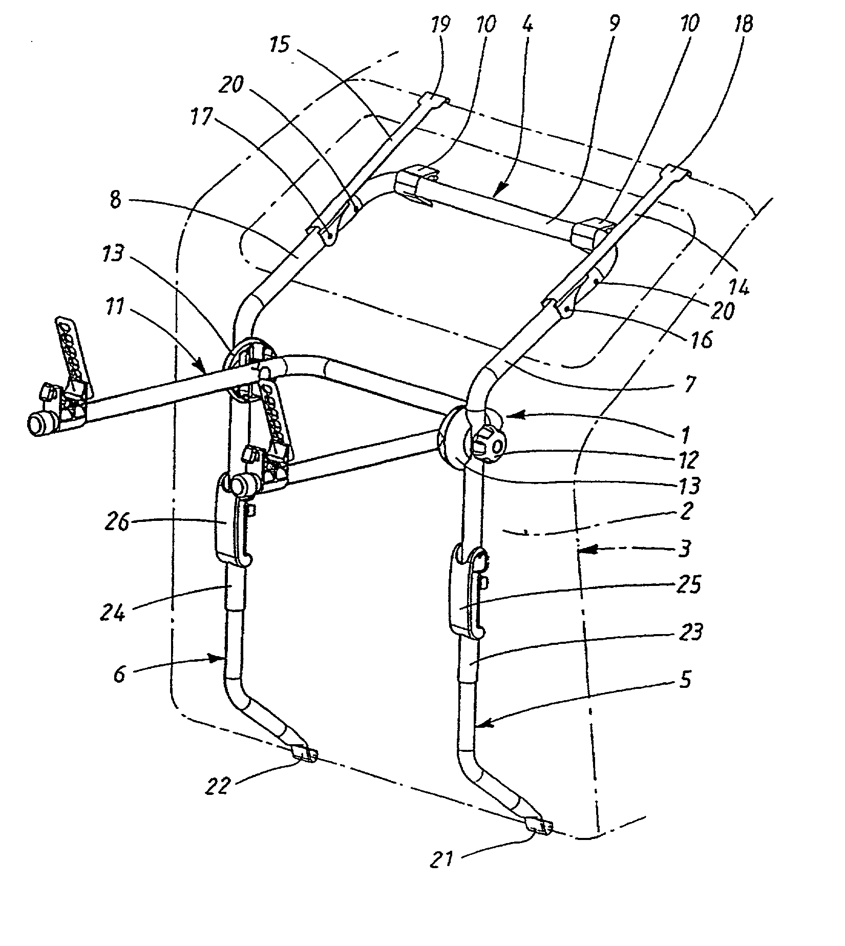
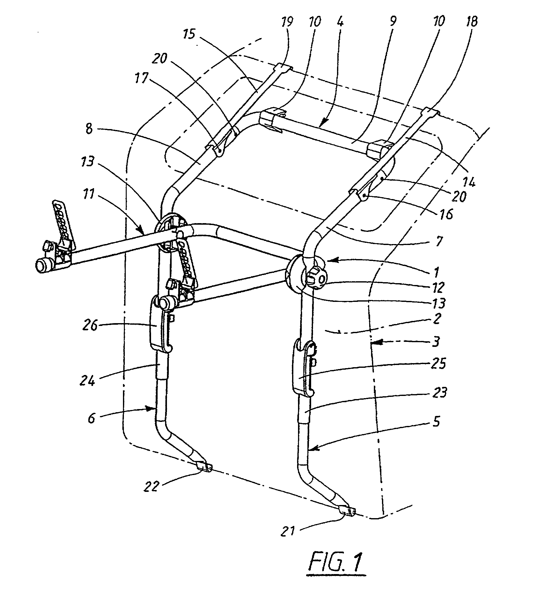
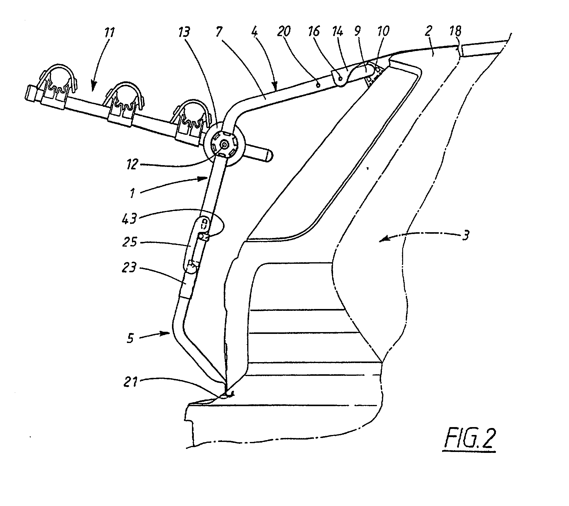
[0018] It may be seen from FIG. 1 that the load carrier of the present invention includes a load-bearing frame 1, also referred to as a rear-mount vehicular load carrier frame which is shown fastened to the rear hatch or door 2 of a motor vehicle 3 which is indicated by dashed lines. The load-bearing frame has an upper frame section or portion 4 and two lower frame sections or portions 5 and 6. These frame sections are constructed of substantially rigid tubing of substantially circular cross-section. The upper frame section 4 is U-shaped with its arms 7 and 8 pointing at least partly downwards. The two arms or arm portions 7 and 8 and the two lower frame sections or elongate legs 5 and 6 are each bent at respective similarly located points in such a manner that the load carrier stands clear of the hatch and is in contact therewith only at the ends of the lower frame sections 5 and 6 and at the base or bight 9 of the U-shaped member where two rubber feet 10 which are press-fit around...


PUM


Abstract

The present invention is concerned with a vehicle-mounted load carrier (1) of the type which is fastened across a door, hatch (2) or the like, preferably at the rear of the vehicle (3). The load carrier comprises a load-bearing frame (4-6) and at least two gripping means (18, 19, 21, 22) disposed on the frame and intended to grip two substantially mutually opposite edges, preferably the top and the bottom edge of the door, and means (25, 26) for tensioning the gripping means across the door by the positive relative displacement thereof towards each other. The novel characteristics of the invention are that the frame is divided into a main section (4), bearing the gripping means (18, 19) for one edge, and at least one tensioning section (5, 6) disposed moveably in relation to the main section and bearing the gripping means (21, 22) for the other edge, and that the main section and the tensioning section are connected to each other in a linearly displaceable fashion, tensioning being achieved by the mutual displacement of the frame sections.

Description

CROSS REFERENCE TO RELATED APPLICATIONS[0001] This is a continuation patent application of International Application Ser. No. PCT / SE00 / 01045 filed May 24, 2000 that designates the U.S. The full disclosure of said application, in its entirety, is hereby expressly incorporated by reference into the present application.BACKGROUND OF INVENTION[0002] 1. Field of Technology[0003] The present invention relates to a vehicle-mounted load carrier; and more particularly, to those types of load carriers that are fastened across a door, hatch or the like, and preferably at the rear of the vehicle.[0004] 2. State of the Art[0005] A vehicular load carrier of the above-mentioned type is disclosed in international patent application WO 97 / 30870. The load carrier of WO 97 / 30870 has a load-bearing frame with two gripping means at the upper end and two gripping means at the lower end. When mounted on a vehicle, the entire load carrier is hooked to a rear hatch. Before installation, however, the distanc...

Claims


Application Information

Patent Timeline
IPC IPC(8): B60R9/06
CPCY10S224/924B60R9/06
Inventor FERMAN, MAGNUS
Owner IND THULE
Learn More