Observation optical system using volume hologram

a volume hologram and optical system technology, applied in the field of image observation optical system, can solve the problems of obstructing observation, affecting image quality, and affecting image quality,

Inactive Publication Date: 2002-05-30
OLYMPUS CORP
View PDF0 Cites 78 Cited by
  • Summary
  • Abstract
  • Description
  • Claims
  • Application Information

AI Technical Summary

Problems solved by technology

However, if the image display apparatus is designed to achieve high image definition and wide field angle using such a prism, chromatic aberration of magnification by the prism itself becomes large, to cause the problem of imaging performance degradation.
As stated above, if high image definition and wide field angle is attempted using a prism, the problem of large chromatic aberration of magnification should occur.
Also, if the relief hologram is used, undesired order rays (0.sup.th order rays, 2.sup.nd order rays) are generated, in addition to the desired order rays, to degrade the image and obstruct observation.
In contrast, in the case of a DOE fabricated by lathing, since its power is symmetric as viewed from the side and as viewed from the top, it cannot compensate a chromatic aberration of magnification derived from an optical member that has a rotationally asymmetric (i.e. asymmetric with respect to at least one of a horizontal plane and a vertical plane) surface.
However, if the power for compensation of the chromatic aberration of magnification

Method used


Image

  • Observation optical system using volume hologram
  • Observation optical system using volume hologram
  • Observation optical system using volume hologram

Examples


second reference example

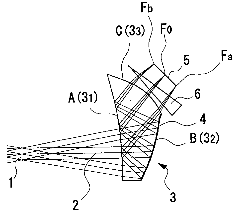
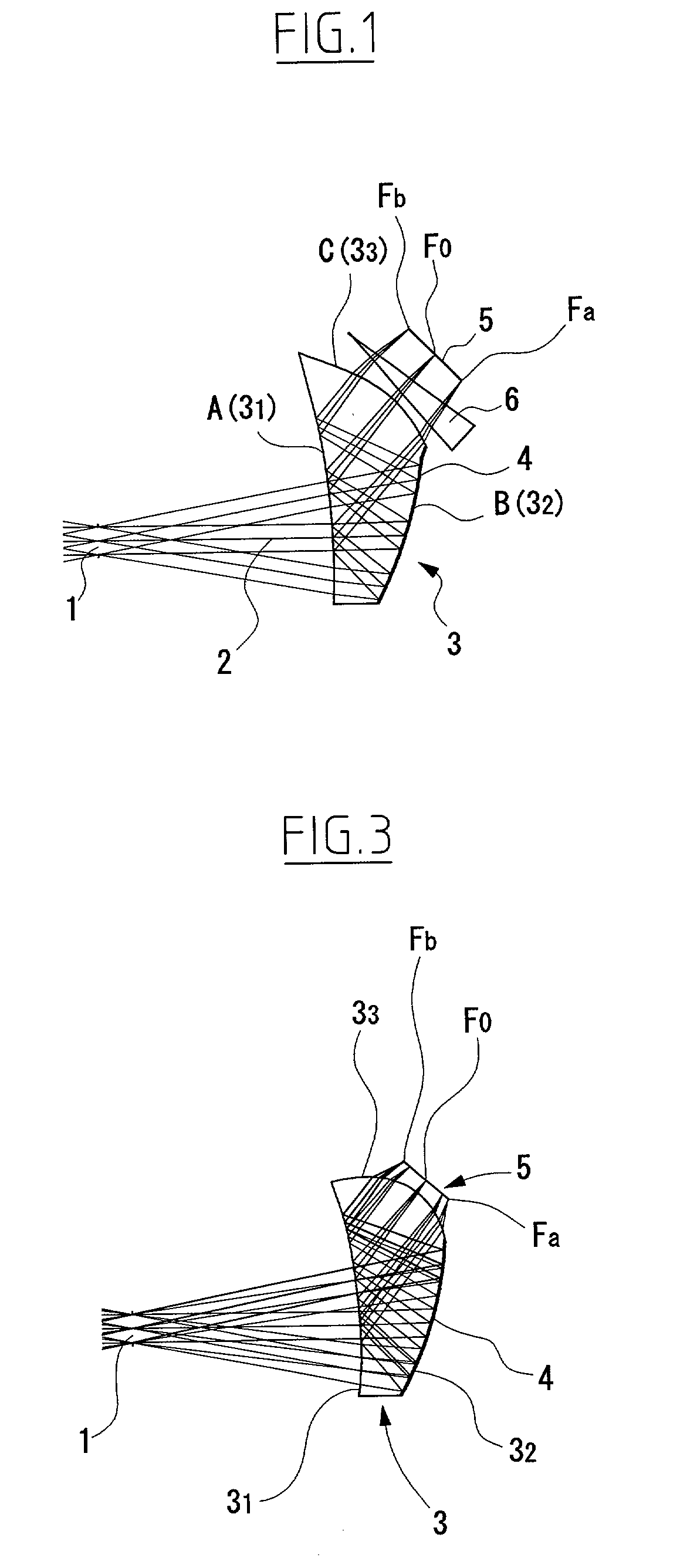
[0223] As shown in FIG. 11, in the image observation optical system of the second reference example, the eyepiece optical system includes a prism 3 having a positive refracting power and a DOE 9.

[0224] The prism 3 is provided with a first surface 3.sub.1 through a third surface 3.sub.3, each of which is shaped as a rotationally asymmetric free curved surface. The first surface 3.sub.1 is constructed and arranged to provide, on the very same surface, a region acting as a first reflecting surface and a region acting as an exit surface. The second surface 3.sub.2 is constructed and arranged as a second reflecting surface. The third surface 3.sub.3 is constructed and arranged as an entrance surface.

[0225] The DOE 9 is disposed between the LCD 5 and the third surface 3.sub.3 of the prism 3.

[0226] According to the present reference example, after being transmitted through the DOE 9 by diffraction, entering the prism via the third surface 3.sub.3 thereof and being reflected at the first su...


PUM


Abstract

An observation optical system comprises an image display element 5 and an eyepiece optical system which introduces an image formed by the image display element 5 to a center of an eye of an observer without forming an intermediate image, so as to allow the observer to observe the image as a virtual image. The eyepiece optical system is constructed and arranged to bend the optical axis using reflecting surfaces so as to be compact. The optical axis lies in a plane, with respect to which the optical system is formed symmetric. The optical system includes a prism 3 having an entrance surface 33, a plurality of curved reflecting surfaces 31, 32 and an exit surface 31. The reflecting surface 32 is provided with a volume hologram (HOE) 4. Whereby, it is possible to provide an image observation optical system which can be made compact enough to be usable as an image display unit for a cellular phone or a portable intelligent terminal, and which can achieve high image definition and wide field angle while controlling chromatic aberration of magnification to be small.

Description

[0001] 1) Field of the Invention[0002] The present invention relates to an image observation optical system. To be specific, it relates to an image observation optical system used in an image display apparatus that can be held on the head or face of an observer and that can be attached to a cellular phone or a portable intelligent terminal.[0003] 2) Description of Related Art[0004] In recent years, development has been energetically made for image display apparatuses, specifically for those to be held on the head or face of individuals for entertaining them with a large image. Also, in accordance with recent popularization of cellular phone and portable intelligent terminal, requirements for large view of graphics or text data on these apparatuses have grown.[0005] As conventional image observation optical systems used in image display apparatuses, there are those as disclosed in Japanese Patent Application Preliminary Publication (KOKAI) No. Hei 7-333551 and Japanese Patent Applica...

Claims


Application Information

Patent Timeline
IPC IPC(8): G02B5/04G02B5/32G02B17/08G02B25/00G02B27/00G02B27/01G02B27/02G09F9/00H04N5/225H04N5/64H04N7/18
CPCG02B27/017G02B2027/0178G02B2027/0132G02B27/0172
Inventor NAKAMURA, TOHRUTAKEYAMA, TETSUHIDE
Owner OLYMPUS CORP
Why Eureka
Try Eureka