Compact cellular phone

a cellular phone and compact technology, applied in the field of compact cellular phones, can solve the problems of radio wave transmission toward a human, deterioration of transmission efficiency, and remarkable degradation of transmission quality

Inactive Publication Date: 2002-06-06
COLTERA
View PDF14 Cites 21 Cited by
  • Summary
  • Abstract
  • Description
  • Claims
  • Application Information

AI Technical Summary

Problems solved by technology

Thus, the radio wave is transmitted toward a human body and a transmission efficiency is deteriorated by the blocking of the radio wave by the human head.
As a result, the transmission quality is rema

Method used


Image

  • Compact cellular phone
  • Compact cellular phone
  • Compact cellular phone

Examples


Embodiment Construction

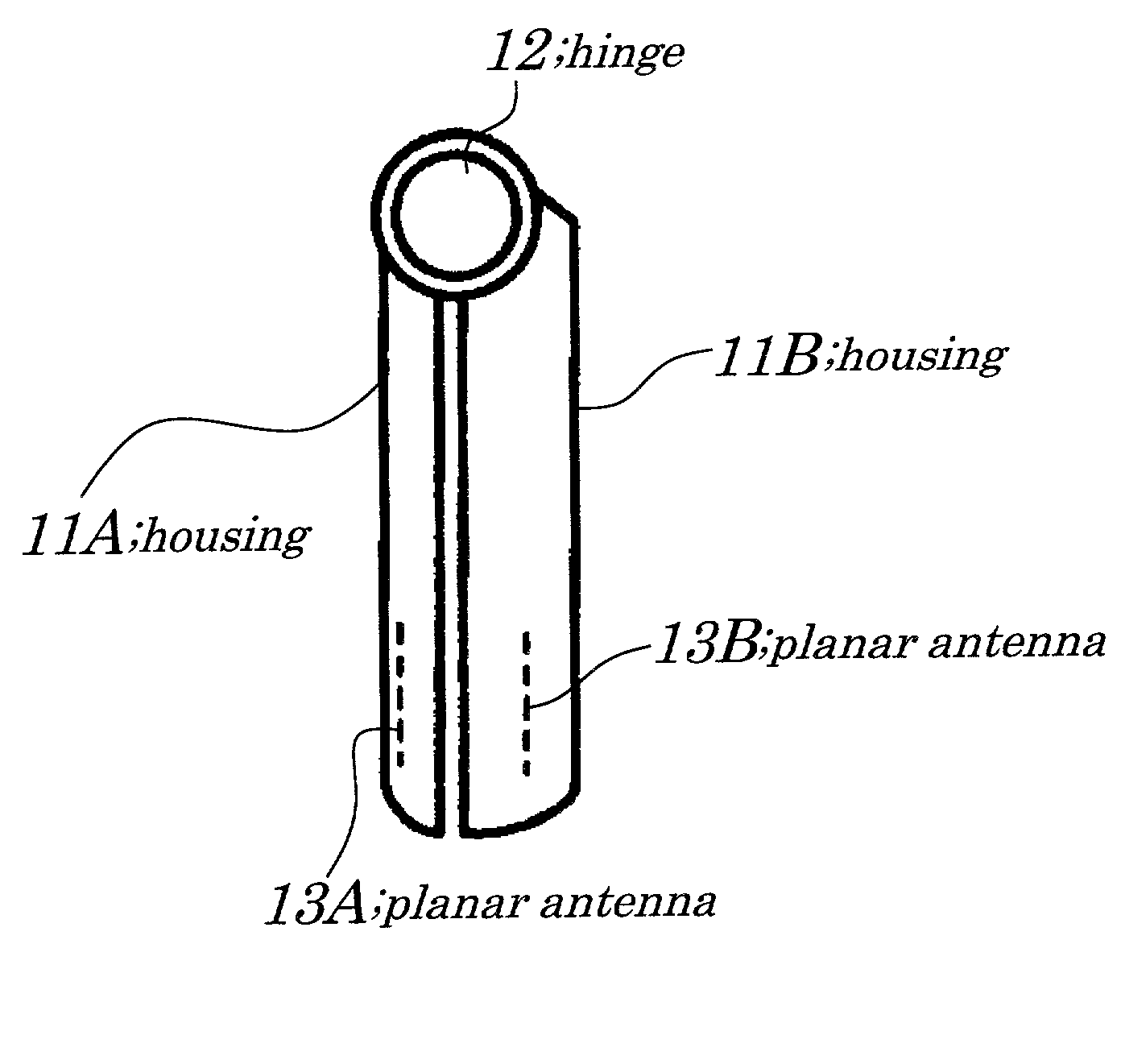
[0035] The example of the present invention will now be described with figures. FIGS. 3A and 3B and FIGS. 4A and 4B show schematic outside views of a compact cellular phone according to the example of the present invention. FIG. 3A is a side elevational view of the compact cellular phone in a closed state, according to the example of the present invention and FIG. 3B is a rear elevational view of the compact cellular phone in the closed state, according to the example of the present invention. FIG.4A is a side elevational view of the compact cellular phone in an open state, according to the example of the present invention and FIG. 4B is a rear elevational view of the compact cellular phone in the open state, according to the example of the present invention. It should be noted that detailed parts that are not directly related to the present invention are not shown in figures and an explanation thereof is omitted.

[0036] A configuration of the compact cellular phone according to the ...


PUM


Abstract

A compact cellular phone with a foldable configuration and two planar antennas having outward directivities are provided inside the compact cellular phone in the foldable configuration. An interval between the two planar antennas provided to a pair of housings is equal to or wider than a width of a human palm in a state in which the compact cellular phone is open. The two planar antennas are planar inverse F-type antennas or patch antennas and impedance around each of the two planar antennas is measured. Then, one of the two planar antennas, which has a preferred transmission characteristic, is selected and used.

Description

[0001] 1. Field of the Invention[0002] The present invention generally relates to a compact cellular phone, and more particularly to the compact cellular phone in which a pair of housings formed in an approximate flat shape is foldably connected by using a hinge.[0003] The present application claims priority of Japanese Patent Application No. 2000-366700 filed on Dec. 1, 2000, which is hereby incorporated by reference.[0004] 2. Description of the Related Art[0005] As shown in FIG. 1A, in a configuration of a conventional cellular phone, a whip antenna 14 has a 1 / 4 wave length or 1 / 2 wave length and is provided to a housing 15. And the whip antenna 14 can be retracted into the housing 15. A coil antenna 16 is wound around dielectrics provided at a top end of the whip antenna 14. When the whip antenna 14 is retracted into the housing 15, the coil antenna 16 remains outside the housing 15 and serves as an antenna for a transmission instead of the whip antenna 14. In addition, a planar ...

Claims


Application Information

Patent Timeline
IPC IPC(8): H01Q1/08H01Q3/24H01Q1/24H01Q9/04H01Q13/08H04B1/38H04B7/06H04B7/08H04M1/02
CPCH01Q1/243H01Q1/245H04B7/0805H01Q21/28H04B7/0608H01Q9/0421
Inventor KURIYAMA, TOSHIHIDEHANKUI, EIJI
Owner COLTERA
Why Eureka
Try Eureka