Built-in type antenna apparatus for mobile terminal

a mobile terminal and built-in technology, applied in the direction of antennas, antenna details, elongated active element feed, etc., can solve the problems of limited thus antenna performance, small space for mounting antennas, and increasing the specific absorption rate of human bodies, so as to reduce the sar and improve the radiation performance of antennas

Inactive Publication Date: 2008-06-05
SAMSUNG ELECTRONICS CO LTD
View PDF2 Cites 16 Cited by
  • Summary
  • Abstract
  • Description
  • Claims
  • Application Information

AI Technical Summary

Benefits of technology

[0020]An aspect of the present invention is to address at least the above-mentioned problems and / or disadvantages and to provide at least the advantages described below. Accordingly, an aspect of the present invention is to provide a built-in antenna apparatus for a mobile terminal which includes a plurality of planar antennas for providing a plurality of feeding points and a plurality of independent radiation patterns, thereby reducing the SAR and improving the radiation performance of the antenna.

Problems solved by technology

Therefore, the space for mounting antenna becomes small.
Further, since the camera module 9, speaker module 8 and the like are additionally mounted as indicated in FIG. 3, the space for mounting the antenna and thus the performance of the antenna, are limited.
As the volume of the built-in antenna is reduced, a Specific Absorption Rate (SAR) of a human body has become an important issue.
In addition, since the current distribution is concentrated on the feeding point, it is difficult to achieve a level of radiation performance of the antenna and the SAR is further increased.

Method used


Image

  • Built-in type antenna apparatus for mobile terminal
  • Built-in type antenna apparatus for mobile terminal
  • Built-in type antenna apparatus for mobile terminal

Examples


Embodiment Construction

[0034]The following description with reference to the accompanying drawings is provided to assist in a comprehensive understanding of exemplary embodiments of the present invention as defined by the claims and their equivalents. It includes various specific details to assist in that understanding but these are to be regarded as merely exemplary. Accordingly, those of ordinary skill in the art will recognize that various changes and modifications of the embodiments described herein can be made without departing from the scope and spirit of the invention. Also, descriptions of known functions and configurations will be omitted for clarity and conciseness.

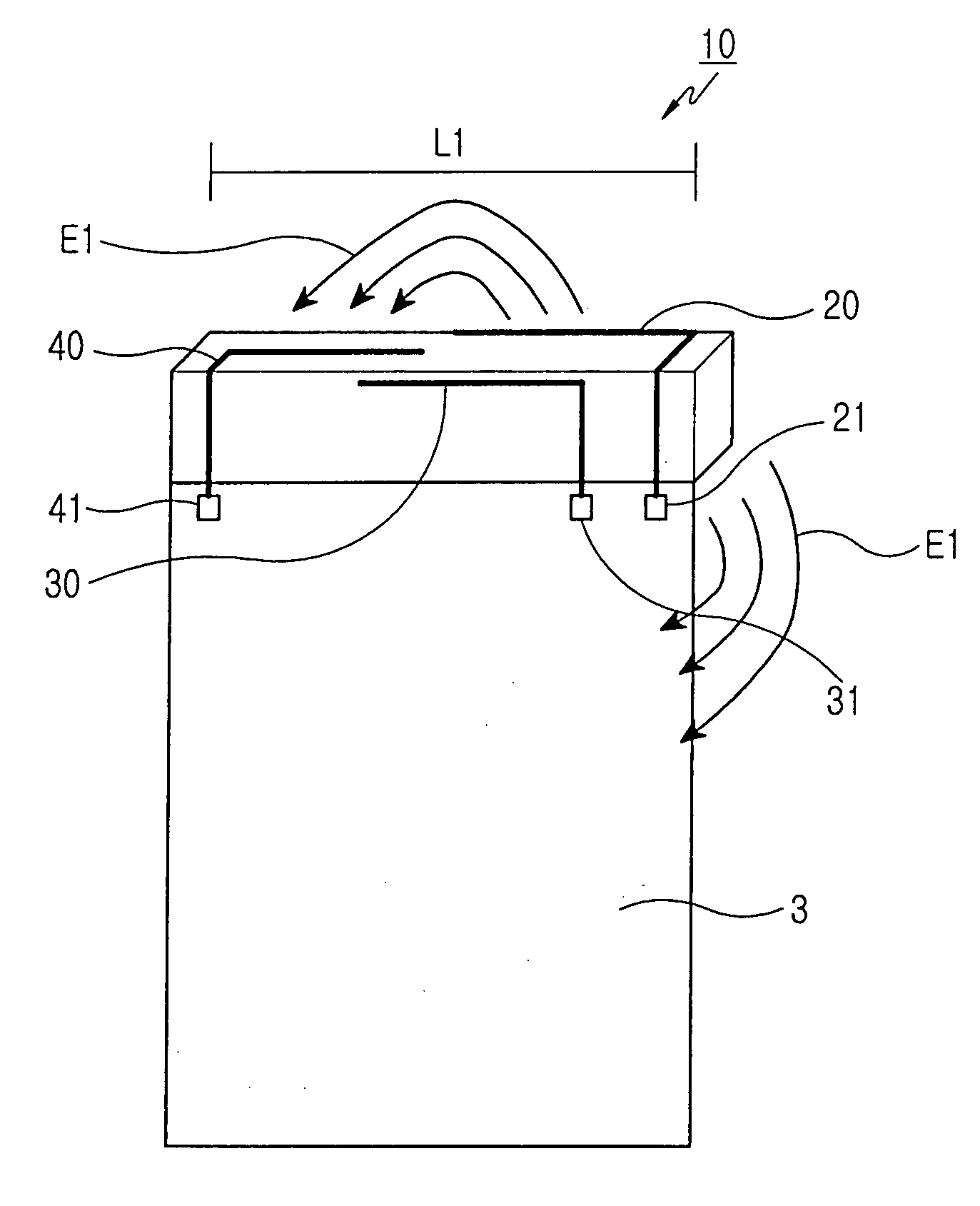
[0035]Referring to FIGS. 4 and 5, a built-in antenna apparatus 10 for a mobile terminal includes a first planar antenna 20, a second planar antenna 30 and a ground stub 40. The first planar antenna 20 located in the terminal has a first feeding point 21 and provides a first radiation pattern. The second planar antenna 30 is located ad...


PUM


Abstract

A built-in antenna apparatus for a mobile terminal is provided. The built-in antenna apparatus includes a first planar antenna having a first feeding point for providing a first radiation pattern, a second planar antenna having a second feeding point for providing a second radiation pattern, the second planar antenna being located adjacent to the first planar antenna, and a ground stub having a ground point for providing a ground pattern, the ground stub placed a distance apart from the first and the second planar antennas.

Description

PRIORITY[0001]This application claims the benefit under 35 U.S.C. §119(a) of a Korean patent application filed on Dec. 5, 2006 in the Korean Industrial Property Office and assigned Serial No. 2006-122431, the entire disclosure of which is hereby incorporated by reference.BACKGROUND OF THE INVENTION[0002]1. Field of the Invention[0003]The present invention relates to a built-in antenna apparatus for a mobile terminal. More particularly, the present invention relates to a built-in antenna apparatus for a mobile terminal, which includes dual planar antennas for providing a feeding point and a radiation pattern, respectively, and a ground stub for providing a ground pattern beyond a distance from the dual planar antennas.[0004]2. Description of the Related Art[0005]Generally, the term “mobile communication apparatus” refers to portable devices which can communicate with other devices using radio frequency. Such mobile communication apparatuses include HHP, CT-2, cellular phones, digital...

Claims


Application Information

Patent Timeline
Patent Type & Authority Applications(United States)
IPC IPC(8): H01Q21/00
CPCH01Q1/243H01Q21/28H01Q19/005H01Q9/42
Inventor SEO, JEONG-AHLEE, JAE-HOPARK, JEONG-WANKIM, YOUNG-HWAN
Owner SAMSUNG ELECTRONICS CO LTD
Why Eureka
Try Eureka