Loop antenna for a mobile terminal capable of reducing specific absorption rate

a mobile terminal and loop antenna technology, applied in the direction of antennas, antenna details, electrical devices, etc., can solve the problems of inability to mount the antenna, meaningless predetermined distance between the antenna and the mobile terminal, and bad influence on the human body

Inactive Publication Date: 2005-10-25
SAMSUNG ELECTRONICS CO LTD
View PDF6 Cites 11 Cited by
  • Summary
  • Abstract
  • Description
  • Claims
  • Application Information

AI Technical Summary

Benefits of technology

[0017]Accordingly, the present invention has been designed to solve the above and other problems occurring in the prior art, and an object of the present invention is to provide a loop antenna for a mobile terminal capable of reducing SAR, which is increased due to current flowing through a printed circuit board, by reducing the current flowing into the printed circuit board from the loop antenna.
[0018]Another object of the present invention is to provide a loop antenna for a mobile terminal capable of maintaining an outer appearance of the mobile terminal even if a connection style and a structure of the loop antenna are varied to reduce SAR, which is increased due to current flowing through a printed circuit board.
[0021]According to the present invention, current flowing through the first line, which is a part of the loop antenna, is transmitted into the second line through the third line connected to the second line without feeding current through the third line, which is a part of the loop antenna. Therefore, current supplied into the first line from the oscillating section is introduced into the second line without being grounded to the oscillating section, and current is not introduced into the printed circuit board having the oscillating section. Accordingly, the SAR, which results from current flowing through the printed circuit board, can be reduced.

Problems solved by technology

If a high SAR is measured, it has a bad influence on the human body.
Thus, the predetermined distance ensured between the antenna and the mobile terminal is meaningless.
Therefore, it is impractical to mount the antenna 12 by using the balun 14.

Method used


Image

  • Loop antenna for a mobile terminal capable of reducing specific absorption rate
  • Loop antenna for a mobile terminal capable of reducing specific absorption rate
  • Loop antenna for a mobile terminal capable of reducing specific absorption rate

Examples


Embodiment Construction

[0029]Preferred embodiments of the present invention will be described in detail hereinbelow with reference to the accompanying drawings. In the following description of the present invention, the same reference numerals are used to designate the same or similar components and a detailed description of known functions and configurations incorporated herein will be omitted when it may make the subject matter of the present invention rather unclear. In addition, it will be understood by those skilled in the art that specific components and structures described in the following description, such as devices forming a circuit, do not intend to limit the scope of the present invention, but intend to explain the present invention.

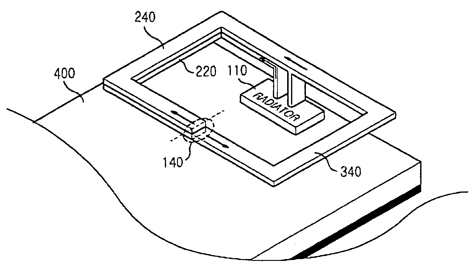
[0030]FIG. 4 is a circuit view of a loop antenna for a mobile terminal capable of reducing SAR, which results from current flowing through a printed circuit board, according to a preferred embodiment of the present invention. As illustrated in FIG. 4, the loop ant...


PUM


Abstract

A loop antenna for a mobile terminal capable of reducing SAR. The loop antenna has three lines. The first line generates and transmits predetermined electric waves upon receiving current from an oscillator for oscillating power and has a connection point to connect an external line thereto. The second line includes a first end connected to a printed circuit board to ground current supplied to the first line and a second end having an opened structure. The third line has a first end connected to one side of the first line through the connection point and a second end connected to one side of the second line coupled to the printed circuit board in order to receive current from the first line through the connection point and transmit current into the second line.

Description

PRIORITY[0001]This application claims priority to an application entitled “Loop Antenna for Mobile Terminal Capable of Reducing Specific Absorption Rate” filed in the Korean Industrial Property Office on Jun. 13, 2003 and assigned Serial No. 2003-38358, the contents of which are hereby incorporated by reference.BACKGROUND OF THE INVENTION[0002]1. Field of the Invention[0003]The present invention relates to an antenna for a mobile phone, and more particularly to an antenna for a mobile phone having an improved structure, which reduces specific absorption rate (hereinafter referred to SAR) with respect to an electronic circuit board, which is connected to the antenna and into which electromagnetic waves are absorbed as power is fed through the antenna.[0004]2. Description of the Related Art[0005]Recently, as wireless mobile terminals are widely used and various electronic industries have developed rapidly, devices for shielding electromagnetic waves that are harmful to the human body ...

Claims


Application Information

Patent Timeline
Patent Type & Authority Patents(United States)
IPC IPC(8): H01Q7/00H01Q1/24
CPCH01Q1/243H01Q1/245H01Q7/00H01Q1/24
Inventor LEE, JU-HYUNGKIM, YONG-JIN
Owner SAMSUNG ELECTRONICS CO LTD
Why Eureka
Try Eureka