Multi-band internal antenna of symmetry structure having stub

a symmetry structure and internal antenna technology, applied in the structural form of radiating elements, elongated active elements, resonance antennas, etc., can solve the problems of easy damage to the antenna, difficult assembly process and part management, and the antenna that is one of the largest parts of the wireless communication terminal, so as to reduce the size of the antenna, reduce the sar, and increase the bandwidth of the high frequency band in the operating frequency of the antenna

Inactive Publication Date: 2010-08-24
ELECTRONICS & TELECOMM RES INST
View PDF14 Cites 11 Cited by
  • Summary
  • Abstract
  • Description
  • Claims
  • Application Information

AI Technical Summary

Benefits of technology

[0014]According to the present invention, an antenna size can be reduced by implementing a loop antenna in a stack structure.
[0015]Also, a bandwidth of a high frequency band in an operating frequency of the antenna can be greatly expanded using a stub connected to a top patch.
[0016]In addition, by configuring an antenna patch in a bilateral symmetrical structure, a current density is uniformly distributed to thereby reduce SAR. Further, it is possible to obtain omni-directional radiation pattern with respect to an entire operating frequency (low frequency band and high frequency band) of the antenna.

Problems solved by technology

As the wireless communication terminal is miniaturized and lightweight, the antenna that is one of the largest parts of the wireless communication terminal tends to be smaller, considering the receive sensitivity and harmfulness of electromagnetic wave.
Since the external antenna requires a lot of parts at a region contacting with the antenna, its assembly process and part management are difficult.
The antenna may be easily damaged due to an external impact.
Also, since orientation and gain of the antenna is insufficient, high-quality of communication cannot be secured.
However, the PIFA also has a narrow bandwidth and a current density is condensed at a specific location, resulting in high specific absorption rate (SAR).
However, since the loop antenna using half wavelength is very long, there is a limitation in using the loop antenna as the internal antenna of the wireless communication terminal.
Therefore, there is a difficulty in operating the loop antenna as an actual multi-band antenna.
However, these antennas are limited to the monopole antenna or the PIFA and have not been applied to the loop antenna till now.
As described above, the general internal antennas (monopoly antenna, loop antennas, and PIFAs) have limitation in size when implementing them in the built-in type.
Therefore, it is difficult to obtain omni-directional radiation patterns.

Method used


Image

  • Multi-band internal antenna of symmetry structure having stub
  • Multi-band internal antenna of symmetry structure having stub
  • Multi-band internal antenna of symmetry structure having stub

Examples


Embodiment Construction

[0026]Other objects and aspects of the invention will become apparent from the following description of the embodiments with reference to the accompanying drawings, which is set forth hereinafter.

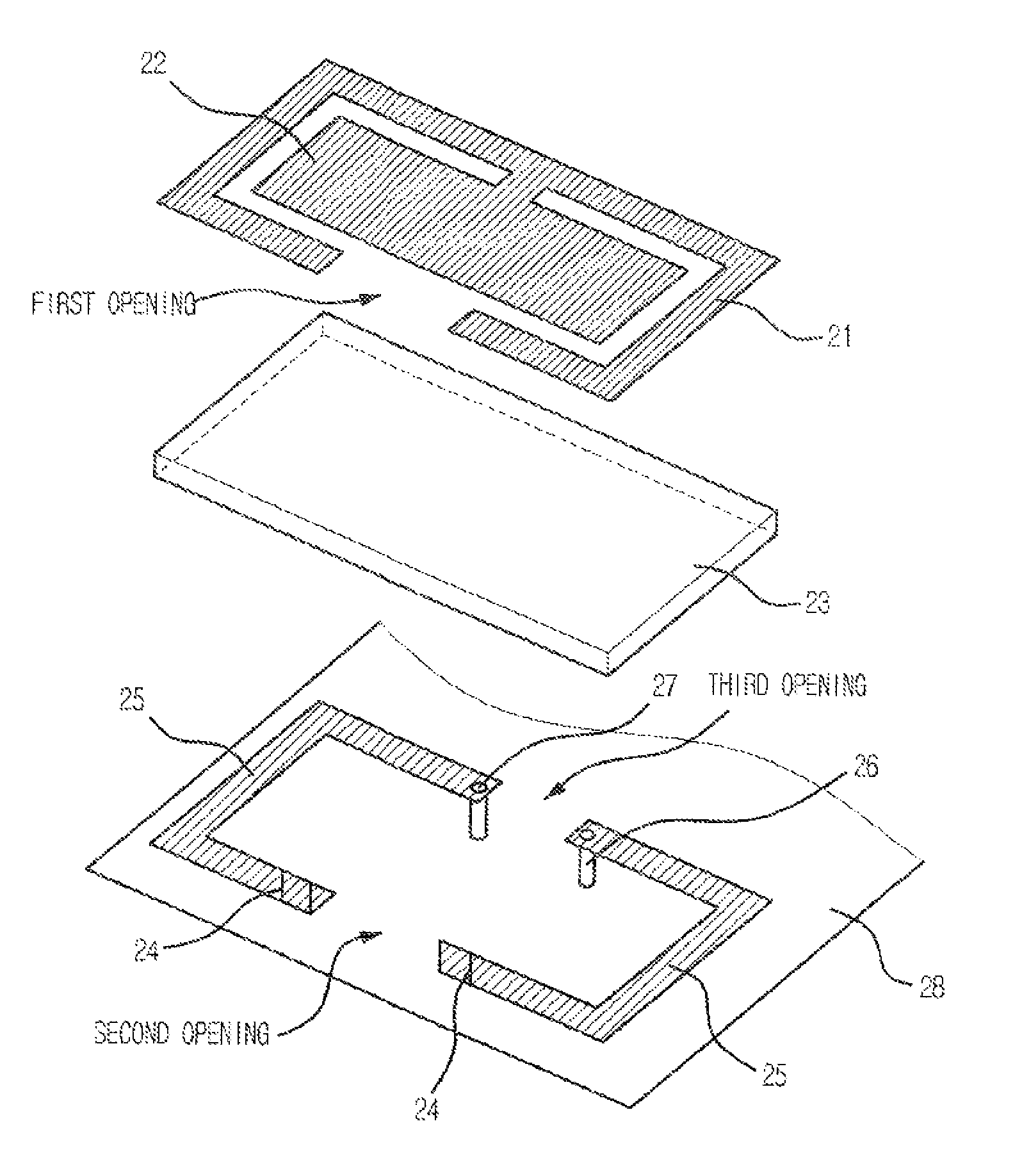
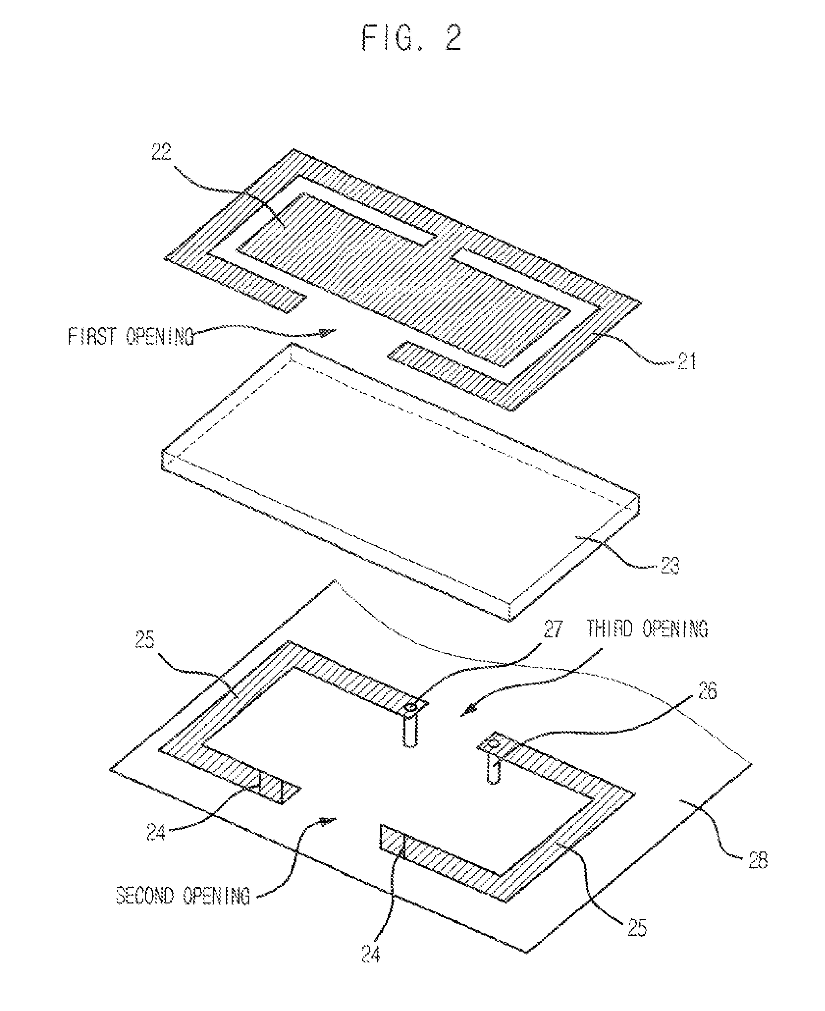
[0027]FIG. 2 is a diagram of a multi-band internal antenna of a symmetry structure having a stub in accordance with an embodiment of the present invention.

[0028]Referring to FIG. 2, the multi-band internal antenna includes a top patch 21, a stub 22, an intermediate part 23, a connecting part 24, a bottom patch 25, a feeder unit 26, a shorting part 27, and a ground part 28.

[0029]The top patch 21 is disposed an upper portion of an antenna and finally radiates signals from the bottom patch 25 to the outside. The top patch 21 is not a completely closed loop but a loop shape of which one side is opened. Hereinafter, this portion will be referred to as a first opening.

[0030]The stub 22 is connected to an opposite side of the first opening in the top patch 22.

[0031]The stub 22 expands bandwidth of...


PUM


Abstract

A multi-band internal antenna includes a top patch defining a first loop that defines a space therein and a first opening; a stub provided within the space defined by the first loop; a bottom patch provided below the top patch and having a first section and a second section connected to a feeder part and a shorting part, respectively, the bottom patch defining a second loop and second and third openings, the second and third openings being provided on opposing sides of the second loop so that the first and second sections of the bottom patch are separated from each other; and a first connecting part and a second connecting part connecting a first portion and a second portion of the top patch, respectively, to the first section and the second section of the bottom patch to transmit a signal from the bottom patch to the top patch.

Description

[0001]This application is a National Stage Application of PCT Application No. PCT / KR05 / 02116, filed on Jul. 4, 2005.TECHNICAL FIELD[0002]The present invention relates to multi-band internal antenna of a symmetry structure having stub; and, more particularly, to a multi-band internal antenna of a symmetry structure having stub, in which a size of the internal antenna can be reduced by stacking loop antennas, a broadband characteristic can be obtained in a high frequency band by connecting the stub to a top patch of the antenna, and a reduced SAR and an omni-directional radiation pattern can be obtained by configuring an antenna patch in a symmetry structure.BACKGROUND ART[0003]In general, an antenna is installed wireless communication terminals (mobile terminal, personal communication system (PCS), personal digital assistant (PDA), IMT-2000 terminal, wireless LAN terminal, smart phone, etc.) and receives reception signals from the outside and radiates transmission signals to the outs...

Claims


Application Information

Patent Timeline
Patent Type & Authority Patents(United States)
IPC IPC(8): H01Q1/38
CPCH01Q7/00H01Q5/357H01Q9/0421H01Q9/0414H01Q13/08
Inventor KIM, BYUNG-CHANCHOI, JAE-ICKLEE, BYUNG-JEJUNG, BYUNG-WOONRHYU, HAN-PHILYU, BYUNG-GIL
Owner ELECTRONICS & TELECOMM RES INST
Why Eureka
Try Eureka