Wireless unit antenna apparatus and mobile wireless unit

a wireless unit and antenna technology, applied in the direction of resonant antennas, independent non-interfering antenna combinations, antenna earthings, etc., can solve the problems of increasing the cost of each the distance between front and back surfaces of the mobile wireless units cannot be reduced, and the mobile wireless unit cannot be downsized. , to achieve the effect of reducing the sar, reducing the sar, and reducing the sar

Inactive Publication Date: 2010-12-14
PANASONIC CORP
View PDF8 Cites 11 Cited by
  • Summary
  • Abstract
  • Description
  • Claims
  • Application Information

AI Technical Summary

Benefits of technology

[0009]It is, therefore, an object of the present invention to provide an antenna apparatus for a wireless unit, and a mobile wireless unit, each of which exhibits a reduced SAR without an additional component for reducing the SAR, and which can be downsized and constructed so as to reduce the distance between front and back surfaces of the mobile wireless unit.
[0032]The antenna apparatus for a wireless unit and the mobile wireless unit according to the present invention is capable of reducing the SAR in the frequency band of the first antenna element.

Problems solved by technology

If the method disclosed in Patent Document 1 is used to reduce the SAR, the mobile wireless unit cannot be downsized, and the distance between front and back surfaces of the mobile wireless unit cannot be reduced.
In this case, a component for reducing the SAR needs to be added, resulting in an increase in the cost of each of the mobile wireless units.

Method used


Image

  • Wireless unit antenna apparatus and mobile wireless unit
  • Wireless unit antenna apparatus and mobile wireless unit
  • Wireless unit antenna apparatus and mobile wireless unit

Examples


first embodiment

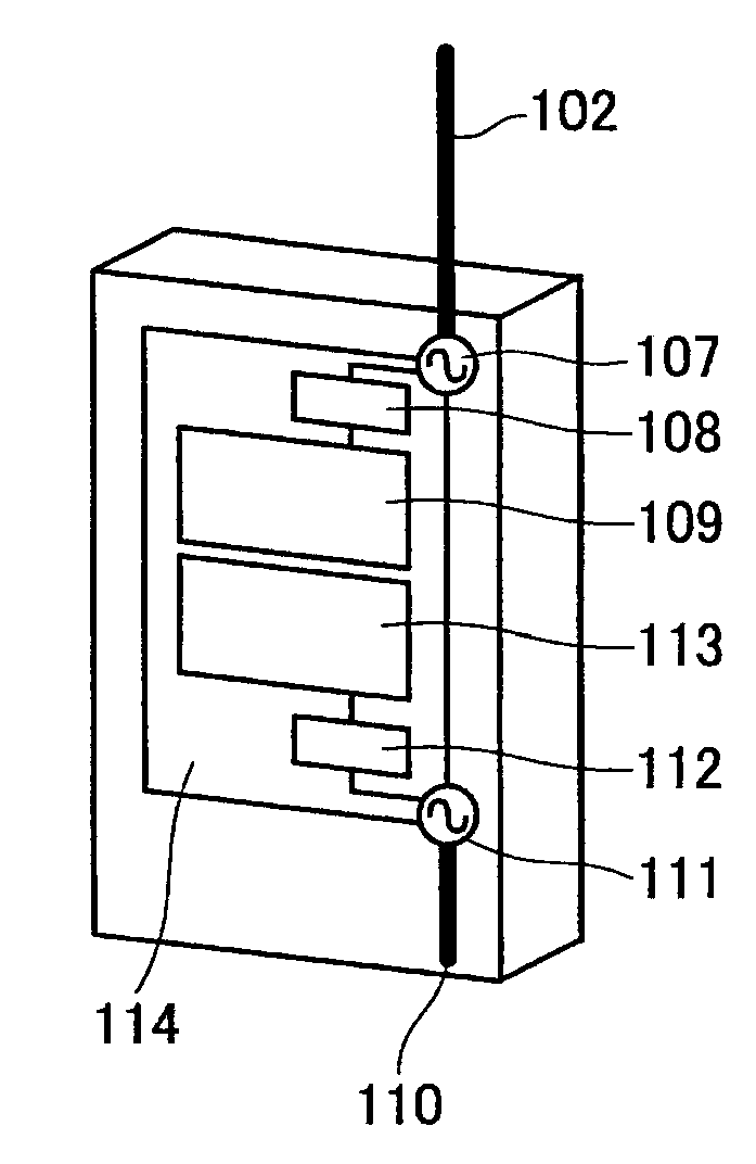
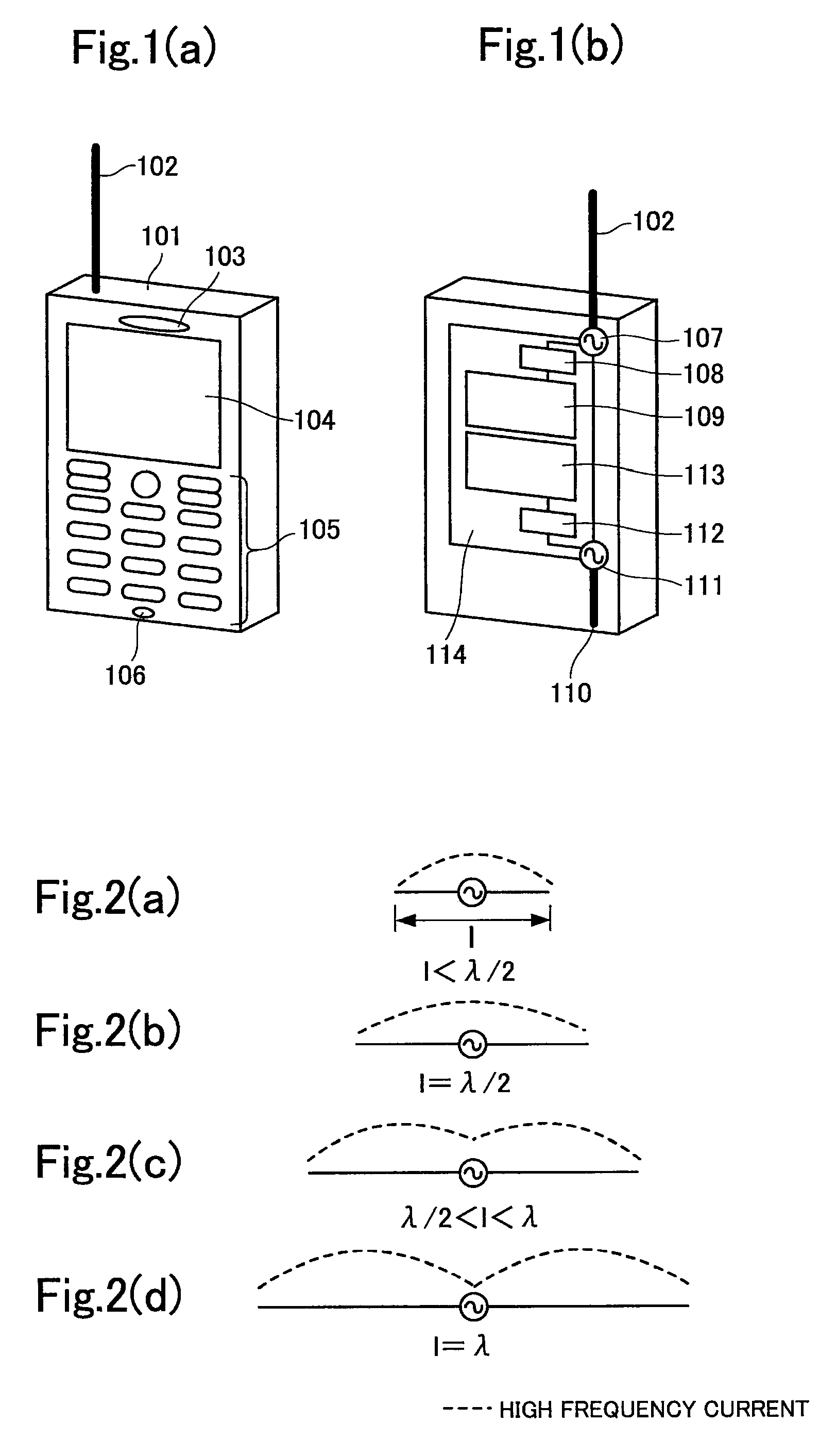
[0057]FIGS. 1(a) and 1(b) are diagrams each showing an outline construction of a mobile wireless unit according to the first embodiment of the present invention. FIG. 1(a) is a front view of the mobile wireless unit, and FIG. 1(b) is a partially perspective view of the back of the mobile wireless unit. The mobile wireless unit shown in FIGS. 1(a) and 1(b) includes a first antenna element 102 having an electrical length, which is 0.21 wavelength of a first frequency band. The first antenna element 102 is designed to transmit and received an electromagnetic wave having a frequency in the first frequency band, and to extend outside a case 101. As shown in FIG. 1(a), the mobile wireless unit includes, on a front surface of the case 101, a receiver 103 for outputting a sound from a calling terminal, a display section 104 for displaying characters such as a phone number, an input section 105 for inputting a phone number and a character, and a transmitter 106 for receiving a voice of a use...

second embodiment

[0067]FIGS. 6(a) and 6(b) are diagrams each showing an outline construction of the mobile wireless unit according to the second embodiment of the present invention. FIG. 6(a) is a front view of the mobile wireless unit, and FIG. 6(b) is a partially perspective view of the back of the mobile wireless unit. As shown in FIGS. 6(a) and 6(b), the mobile wireless unit according to the second embodiment includes a first antenna element 202 having an electrical length of 0.21 wavelength of the first frequency band. The first antenna element 202 is designed to extend outside a case 201. As shown in FIG. 6(a), the mobile wireless unit according to the second embodiment includes, on a front surface of the case 201, a receiver 203 for outputting a sound from a calling terminal, a display section 204 for displaying characters such as a phone number, an input section 205 for inputting a phone number and a character, and a transmitter 206 for receiving a voice of a user.

[0068]As shown in FIG. 6(b)...

third embodiment

[0078]FIGS. 10(a) and 10(b) are diagrams each showing an outline construction of a mobile wireless unit according to the third embodiment of the present invention. FIG. 10(a) is a front view of the mobile wireless unit, and FIG. 10(b) is a partially perspective view of the back of the mobile wireless unit. As shown in FIGS. 10(a) and 10(b), the mobile wireless unit according to the third embodiment includes a first antenna element 302 having an electrical length of 0.12 wavelength of the first frequency band. The mobile wireless unit according to the third embodiment includes, on the front surface of the case 301, a receiver 303 for outputting a sound from a calling terminal, a display section 304 for displaying characters such as a phone number, an input section 305 for inputting a phone number and a character, and a transmitter 306 for receiving a voice of a user as shown in FIG. 10(a).

[0079]The antenna apparatus according to the third embodiment includes, in the case 301, a first...


PUM


Abstract

The present invention provides an antenna apparatus for a wireless unit, the antenna apparatus exhibiting a reduced specific absorption rate (SAR) without an additional component for reducing the SAR, which is the amount of energy of an electromagnetic wave absorbed by a human body. The antenna apparatus comprises a board 114 serving as a ground plate of an antenna, a first antenna element 102 transmitting and receiving an electromagnetic wave in a first frequency band and provided on the board 114 through the first feeder 107, and a second antenna element 110 transmitting and receiving an electromagnetic wave in a second frequency band and provided on the board 114 through the first feeder 111, wherein the total of an electrical length between the first and second feeders 107 and 111, an electrical length of the first antenna element 102, and an electrical length of the second antenna element 110 is larger than a half wavelength of the first frequency band and equal to or smaller than one wavelength of the first frequency band.

Description

CROSS REFERENCE TO RELATED APPLICATIONS[0001]The present application is a 371 of PCT / JP2006 / 317655 filed Sep. 6, 2006, claims priority under Title 35, United States Code 119(a-d) of Japan 2005-262259 filed Sep. 9, 2005.TECHNICAL FIELD OF THE INVENTION[0002]The present invention relates to an antenna apparatus for a wireless unit and a mobile wireless unit.BACKGROUND OF THE INVENTION[0003]In relation to the conventional wireless units of this type, there have been reported adverse effects on a human body due to exposure of the human body to a high-intensity electromagnetic wave in recent years. The reported adverse effects include an elevation of the temperature of the human body, and stimulation of a nerve in the human body. In consideration of the adverse effects on the human body, a regulation has been established since June, 2002 to ensure that a specific absorption rate (SAR) must be 2 mW / g or less. The SAR is the amount of energy of an electromagnetic wave transmitted by a wire...

Claims


Application Information

Patent Timeline
Patent Type & Authority Patents(United States)
IPC IPC(8): H01Q1/24
CPCH01Q1/242H01Q1/48H01Q1/521H01Q9/0421H01Q9/30H01Q21/28
Inventor IMANO, DAIGOKIKUCHI, HIRONORI
Owner PANASONIC CORP
Why Eureka
Try Eureka