Tongue lifting device for tongue blades made of stock rail profiles

a technology of stock rail profiles and lifting devices, which is applied in the direction of metal-working holders, positioning devices, supports, etc., can solve the problems of inability to lift and shift tongues made of stock rail profiles, and achieve the effect of improving the alignment of the device and simple manner

Inactive Publication Date: 2002-06-27
CARL DAN PEDDINGHAUS
View PDF0 Cites 10 Cited by
  • Summary
  • Abstract
  • Description
  • Claims
  • Application Information

AI Technical Summary

Benefits of technology

0012] In a preferred embodiment, mount for the rolling device comprises support braces which are adapted to be in abutment with said lumber or concrete tie. As a result, the mount for the rolling device is able to transfer the weight of the tongue blade to the ground. Further, the support braces improve the alignment of the device for lifting a tongue blade according to the invention with the concrete or lumber tie.
0013] Since at least one opening is formed below said rollers in the rolling device mount, water and dirt can run off through this opening preventing a locking of the rollers due to accumulated dirt or ice.
0014] It is further advantageous that a pillow block is integrated into the base plate so that a single part in form of the base plate combines the function of the sliding plate, the tongue lifting means as well as the attachment of the running rail in the tongue lifting device.
0015] In a preferred embodiment, said base plate is a cast part or forged part so that the tongue lifting device according to the invention combining different functions into one component can be manufactured in a cost advantageous manner.
0016] When lining plates are arranged between said base plate and said lumber or concrete tie, the height of the entire tongue lifting device can be adjusted in a simple manner.

Problems solved by technology

In known tongue lifting devices it is not possible for reasons of space that tongues made of stock rail profiles are lifted and shifted.
The reason for this is that when switching railway switches the tongue blades are lifted by a tongue lifting device, in particular a rolling device, which requires some space so that there is not enough space in the vertical direction for the use of tongue blades made of stock rail profiles.

Method used


Image

  • Tongue lifting device for tongue blades made of stock rail profiles
  • Tongue lifting device for tongue blades made of stock rail profiles
  • Tongue lifting device for tongue blades made of stock rail profiles

Examples


Embodiment Construction

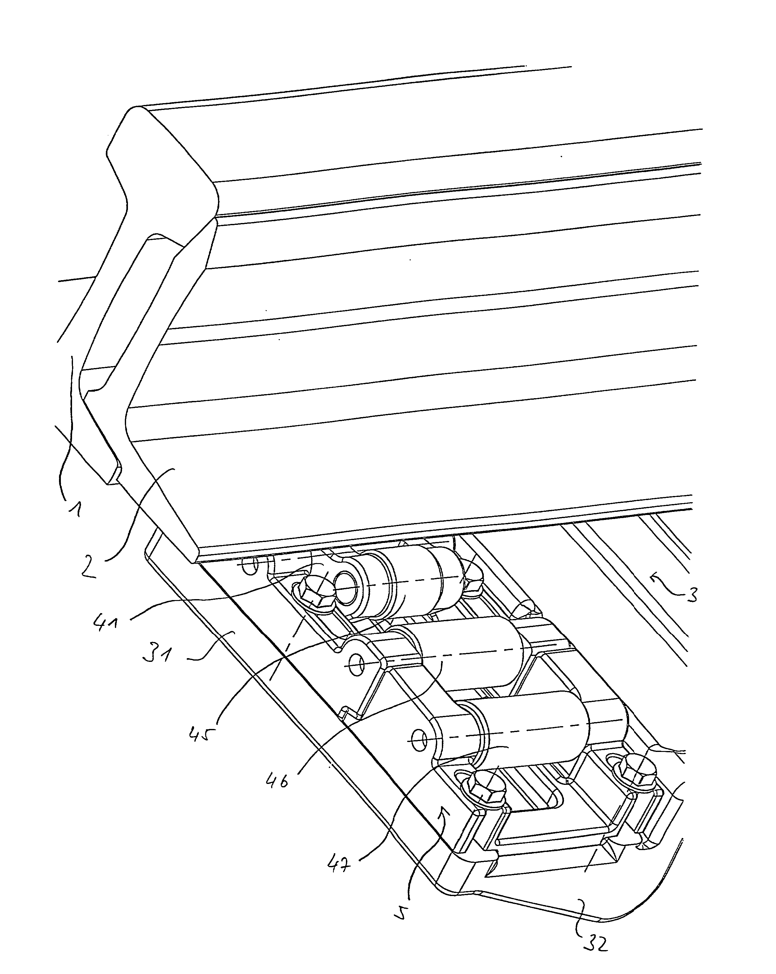
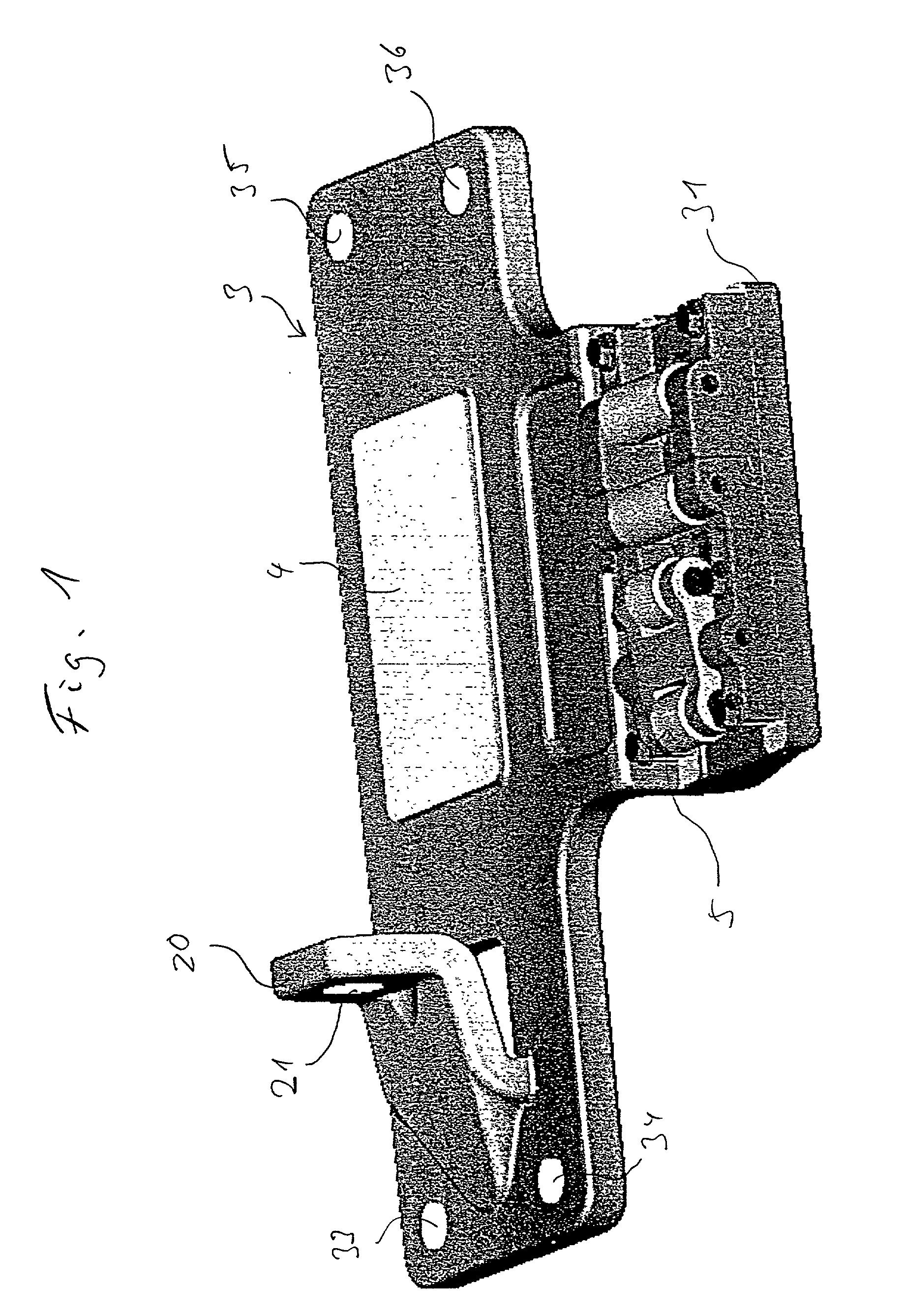
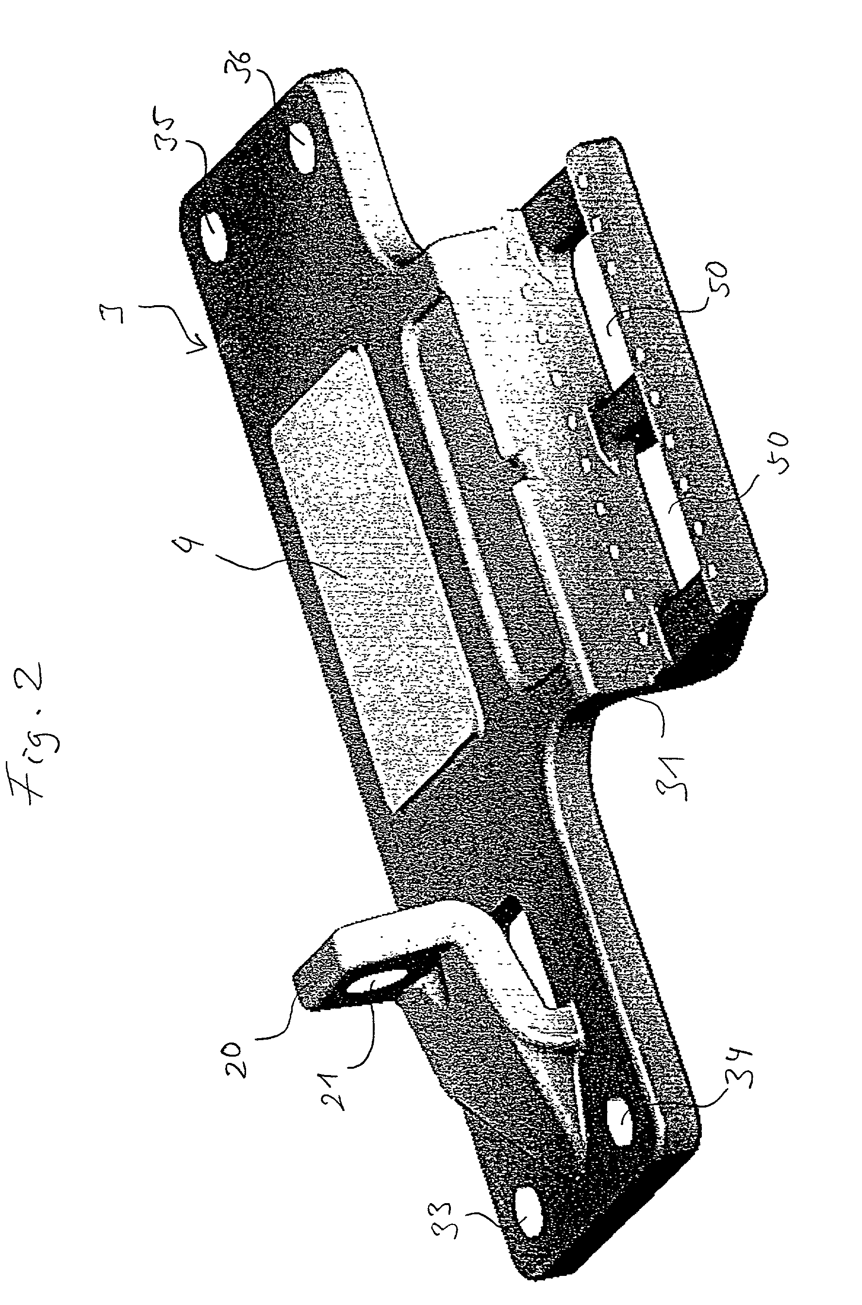
[0024] The tongue lifting device shown in FIG. 1 comprises a base plate 3 which serves as rail support for a running rail 1 not shown in FIG. 1. The base plate 3 is attached via bores 33, 34, 35 and 36 to a lumber tie or concrete tie or the like. The area of the base plate 3 extending between the bores 33, 34, 35 and 36 lies transverse to the running rail 1 on the concrete or lumber tie. In this area there is a sliding surface 4 for the sliding placement of a tongue blade 2 not shown in FIG. 1. Further a pillow block 20 is provided in this area of the base plate 3 having a bore 21, through which the pillow block 20 is screwed onto the base of the running rail 1. The pillow block 20 is preferably designed integrally with the base plate 3, which is cast or forged.

[0025] A mount 31 for the rolling device is provided on the base plate 3 along the side of the area of the base plate 3, which, in the mounted state is disposed above the lumber or concrete tie. The mount 31 for the rolling d...


PUM


Abstract

A device for lifting a tongue blade (2) of points made of stock rail profiles, with a rolling device (5) includes a plurality of rollers (44, 45, 46, 47), sliding knobs, balls or the like which are orientated essentially parallel to a running rail (1), which transport said tongue blade (2) in a direction transversely to the running rail (1), and a base plate (3) which serves as rail support for said running rail (1) and which is mountable on a concrete or lumber tie, wherein said rolling device (5) can be arranged beside a longitudinal side wall of said lumber or concrete tie and is displaced downwardly such that the base of said running rail (1) and the base of said tongue blade (2) lie essentially at the same horizontal level.

Description

[0001] The present invention relates to a tongue lifting device for tongue blades of a railway switch made of stock rail profiles.[0002] 1. Background Art[0003] In known tongue lifting devices it is not possible for reasons of space that tongues made of stock rail profiles are lifted and shifted. The reason for this is that when switching railway switches the tongue blades are lifted by a tongue lifting device, in particular a rolling device, which requires some space so that there is not enough space in the vertical direction for the use of tongue blades made of stock rail profiles.[0004] A prior art tongue lifting device for lifting the tongue blades of points or a switch by means of a rolling device is published as European patent specification EP 0 495 160 B1. Reference is herewith made to this European patent specification 0 495 160 B1, stemming from the applicant, as regards the function of the rolling device.[0005] 2. Disclosure of the Invention[0006] It is the object of the ...

Claims


Application Information

Patent Timeline
Patent Type & Authority Applications(United States)
IPC IPC(8): E01B7/02
CPCE01B2202/046E01B7/02
Inventor LESEMANN, BERND
Owner CARL DAN PEDDINGHAUS
Why Eureka
Try Eureka