Method for injection-molding a propeller fan

a propeller fan and injection molding technology, which is applied in the field of injection molding a propeller fan, can solve the problems of lowering the moldability of the product, incurring additional cost, and difficult to obtain a uniform molded product, and achieves the effect of lowering the amount of unbalance involved

Inactive Publication Date: 2002-07-11
IDEMITSU KOSAN CO LTD +2
View PDF0 Cites 91 Cited by
  • Summary
  • Abstract
  • Description
  • Claims
  • Application Information

AI Technical Summary

Benefits of technology

0009] Further, another object of the present invention is to provide a method for projection molding a propeller fan which comprises the steps of providing a movable core at an area corresponding to a thicker portion of a blade section of a propeller fan; after the movable core has been pushed out into a blade space of a mold cavity defined by a fixed-side mold section, movable-side mold section and mova...

Problems solved by technology

A thicker blade profile, being thinner in its peripheral edge portion and thicker in its central and base portions, involves an increased weight, shrinkage and increased cycle time in a general injection-molding process, thus presenting the problem of lowering its moldability and incurring added cost.
Although a foam molding, a blow molding, etc., methods are known as th...

Method used


Image

  • Method for injection-molding a propeller fan
  • Method for injection-molding a propeller fan
  • Method for injection-molding a propeller fan

Examples


example 2

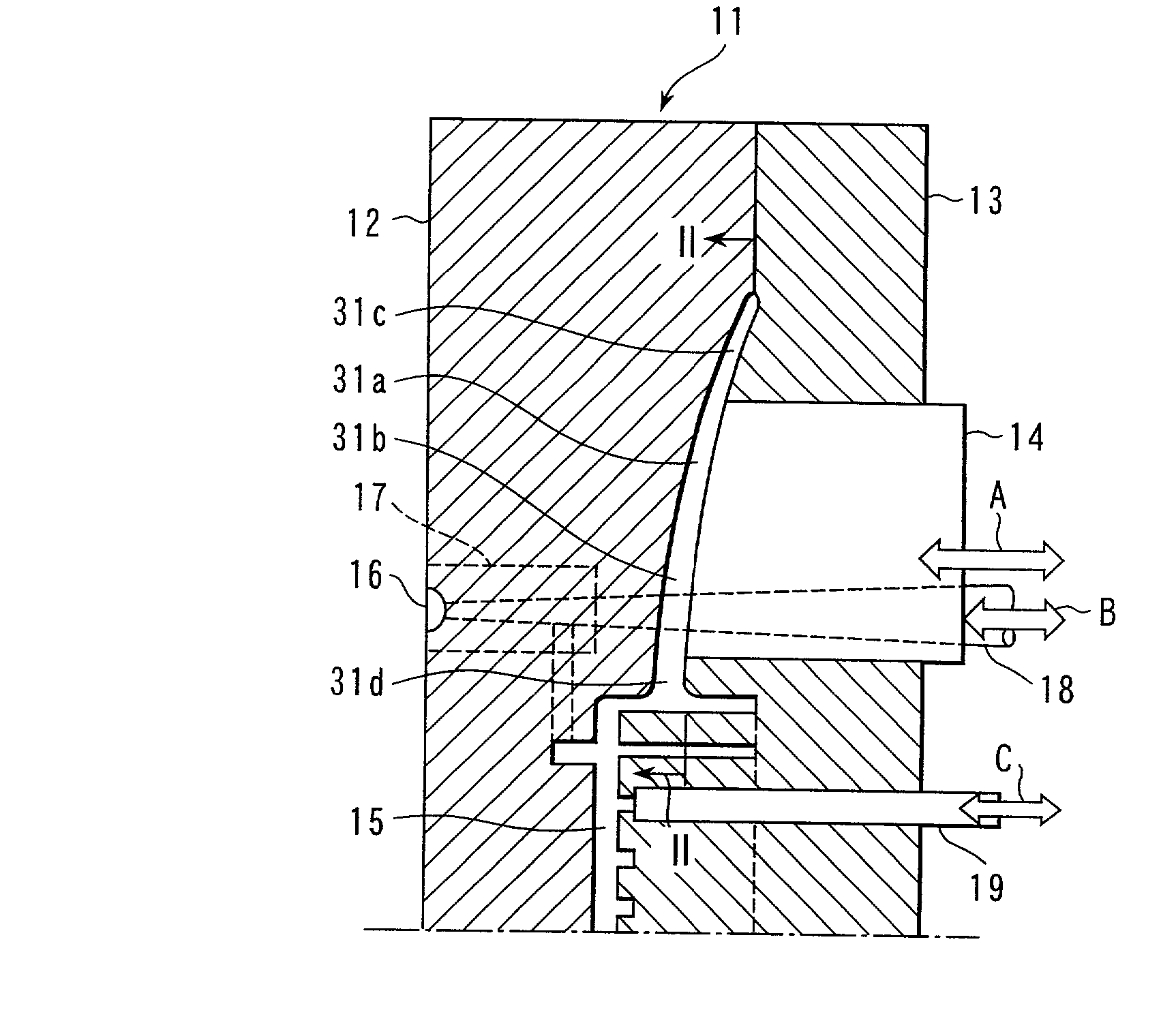
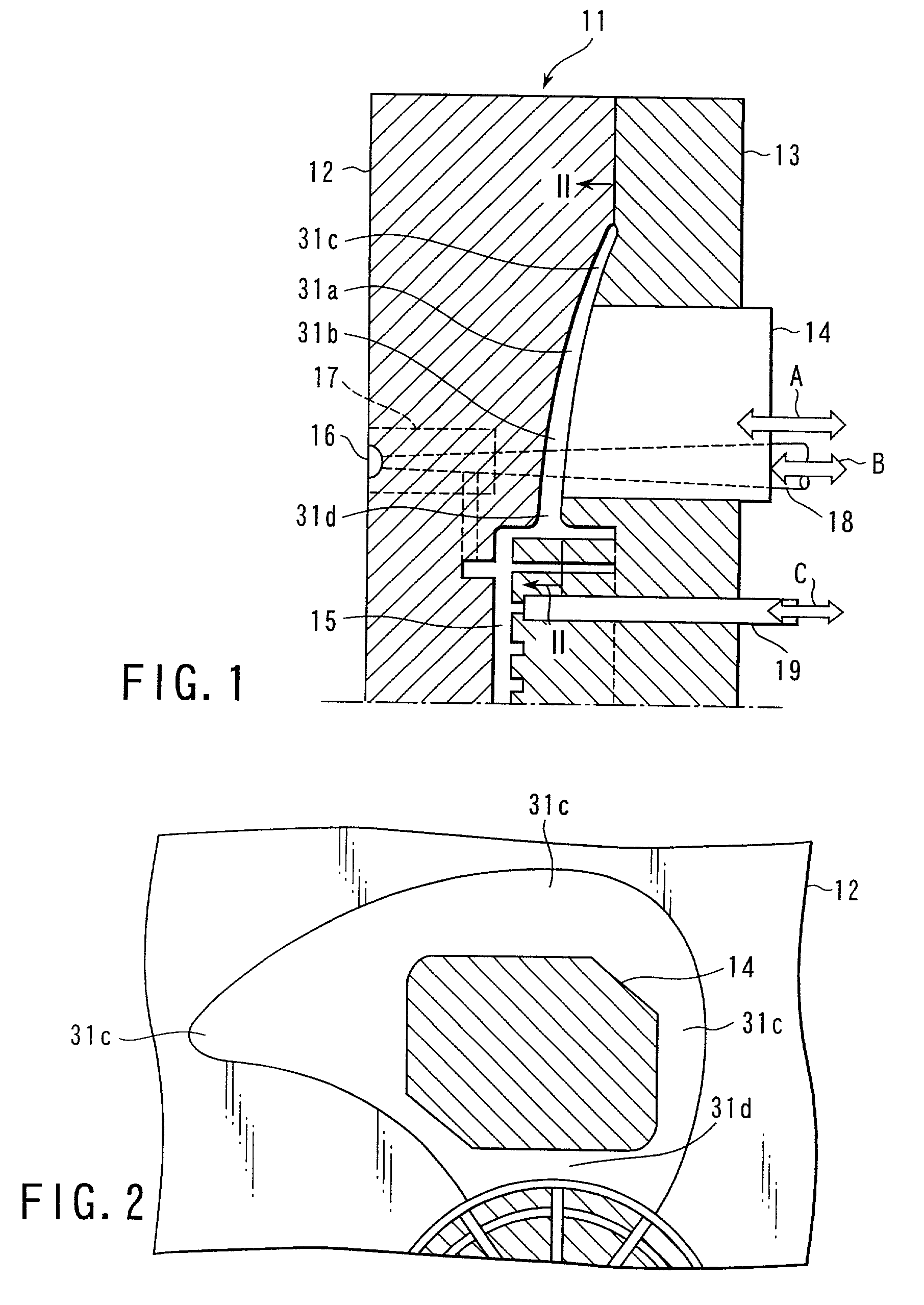
[0038] As set out above in connection with Example 1, after the movable core 14 was pushed out toward a blade section 31a side, the plastic material was forced into the mold cavity conforming to a fan and filled there and the pouring control pin 18 is brought to a closed position. Thereafter, the similar processes as set out above in connection with the processes (3) and (4) of Example 1 were performed to obtain a plastics propeller fan.

[0039] According to the above-mentioned Example it was possible to obtain the same effects as in Example 1.

[0040] Although, in the above-mentioned embodiment, an explanation has been made about the case of using, as the plastics material, a long-fiber reinforced plastics containing glass fibers, etc., having a length of above 3 mm, the present invention is not restricted thereto and use may be made of a plastics material obtained by mixing a foaming agent into an ordinary plastics material or a plastics material obtained by mixing a foaming agent in ...


PUM

PropertyMeasurementUnit
Timeaaaaaaaaaa

Abstract

A method for injection-molding a plastics propeller fan by using a fixed-side mold section and movable-side mold section, comprises the steps of providing a movable core at an area corresponding to a thicker portion of a blade section of the propeller fan; after a predetermined amount of plastics material has been injected into a blade space of a mold cavity defined by the fixed-side mold section, movable-side metal section and movable core and conforming to the propeller fan, pushing out the movable core into the mold cavity and, after this step, bringing the movable core back to a normal position conforming to a mold shape defining the blade space and forming a proper fan.

Description

[0001] The present invention relates to a method for injection-molding a propeller fan and, in particular, to a method for injection-molding a plastics propeller fan for use in an air conditioner condenser's cooling fan, ventilator, vehicle radiator's cooling fan, etc.DESCRIPTION OF THE RELATED ART[0002] Conventionally, a fan as shown in FIGS. 3 and 4 is known as a plastics propeller fan. Here, FIG. 3 is a plan view and FIG. 4 is a cross-sectional view taken along line IV-IV in FIG. 3, that is, shows a blade profile.[0003] Conventionally, this kind of propeller fan has been used for the air conditioner condenser's cooling fan, ventilator, vehicle radiator's cooling fan, etc., and has been manufactured mainly using a plastics material.[0004] The blade profile has often been formed with the use of a thin sheet and, in order to improve its aerodynamic characteristics, it is considered effective to use a fan blade having a cross-section as shown in FIG. 4. In this case, however, its cro...

Claims


Application Information

Patent Timeline
IPC IPC(8): B29C44/42B29C45/56
CPCB29C44/428B29C45/561B29C2045/566B29L2031/08B29L2031/087
Inventor SUZUKI, ATSUSHIINOUE, MASASHIKONDOH, FUMIOTODA, NAOKISAKUMA, MATSUOGOUDA, HIROFUMINOMURA, MANABU
Owner IDEMITSU KOSAN CO LTD
Why Eureka
Try Eureka