Disk clamp apparatus
a technology of clamping apparatus and clamping surface, which is applied in the field of clamping apparatus, can solve the problems of reducing the accuracy of recording, difficulty in keeping the surface accuracy of an edge part, and affecting the accuracy of recording
- Summary
- Abstract
- Description
- Claims
- Application Information
AI Technical Summary
Benefits of technology
Problems solved by technology
Method used
Image
Examples
first embodiment
[0050] FIG 3 is an exploded perspective view showing a disk device to which a disk clamp apparatus according to the present invention is applied.
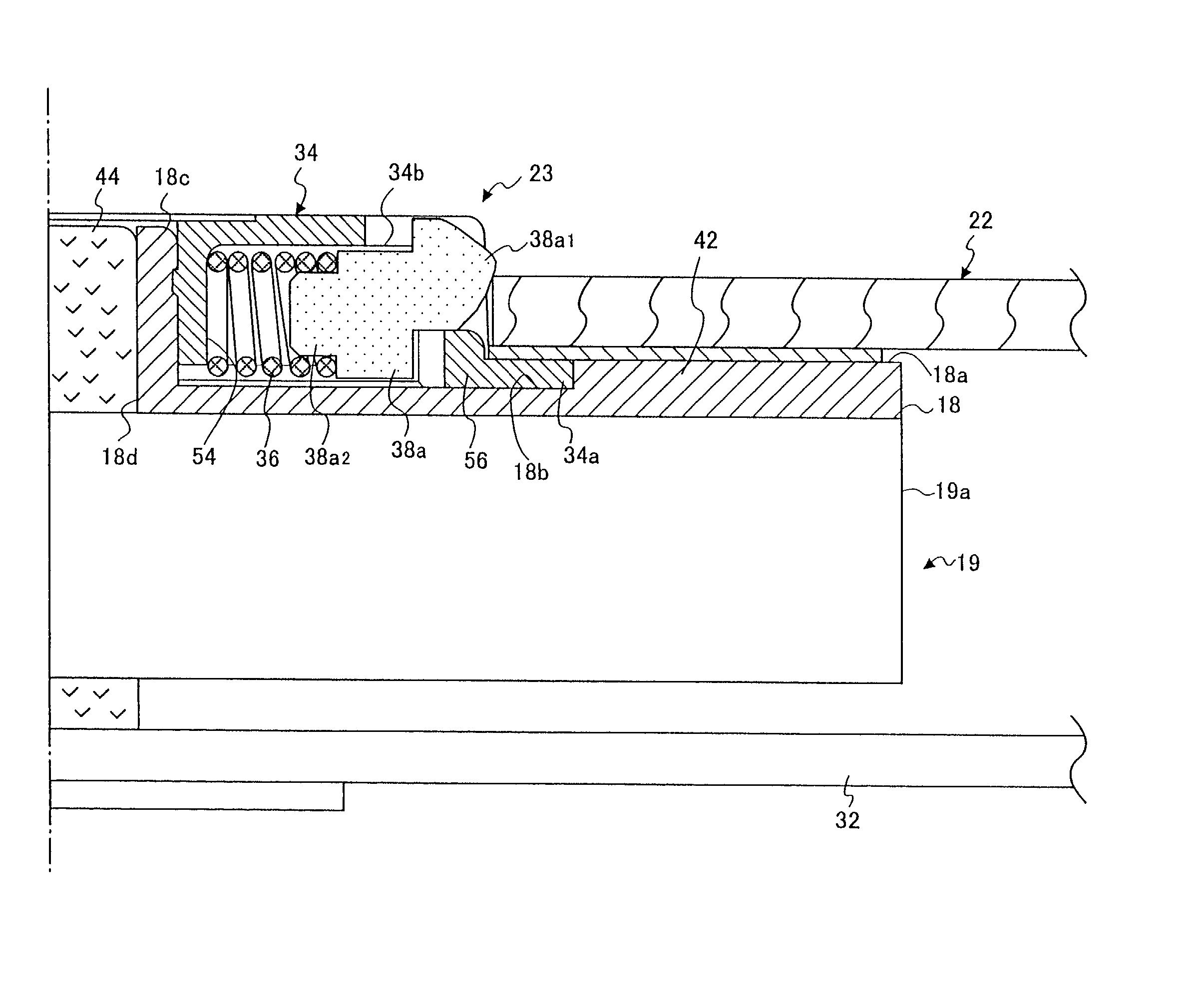
[0051] Referring to FIG. 3, a disk device 11, for instance a CD-ROM drive device, includes a tray 20 supporting a clamp table 18 in a state where the clamp table 18 can be rotated in a space formed between an upper cover 12 and a lower cover 16. A disk clamp apparatus 23 is provided at a center of a clamp table 18. A disk 22 shown as a one doted line in FIG. 3 has an inner circumference clamped by the disk clamp apparatus 23. A disk storage part 24 having a diameter greater than a diameter of the disk 22 is formed around the clamp table 18.
[0052] An optical pick up 26 is provided below the disk storage part 24 as the optical pick up 26 can move in a disk radial direction. Information which is recorded in the disk 22 clamped by the disk clamp apparatus 23 of the clamp table 18 is read out by the optical pick up 26. The optical pick up 26 is ...
second embodiment
[0077] Next, the present invention will be described.
[0078] FIG. 9A is a plan view of a disk clamp apparatus of a second embodiment of the present invention. FIG. 9B is a side sectional view of the disk clamp apparatus of the second embodiment of the present invention. FIG. 10 is a greatly enlarged detailed vertical sectional view of a disk clamp part of a disk clamp apparatus of the second embodiment of the present invention. In this embodiment, parts that are the same as the parts shown in the first embodiment are given the same reference numerals, and explanation thereof will be omitted.
[0079] Referring to FIGS. 9A, 9B and 10, in a disk clamp apparatus of a second embodiment, a friction member 62 fixed on the disk mount surface 18a has an inner diameter having a larger diameter than the inner diameter of the disk 22. A guard part 34a' projecting from an outer circumference of the clamper top 34 in a radial direction is extended to a position which faces to the innermost circumfer...
third embodiment
[0081] Next, the present invention will be described.
[0082] FIG. 11A is a plan view of a disk clamp apparatus of a third embodiment of the present invention. FIG. 11B is a side sectional view of the disk clamp apparatus of the third embodiment of the present invention. FIG. 12 is an enlarged perspective view of a clamper table 18 of a third embodiment. FIG. 13 is an enlarged vertical sectional view of a disk clamp part of the third embodiment. In this embodiment, parts that are the same as the parts shown in the first and second embodiments are given the same reference numerals, and explanation thereof will be omitted.
[0083] Referring to FIGS. 11A, 11B, 12 and 13, according to the disk clamp apparatus of the third embodiment 70, the friction member 42 fixed on the disk mount surface 18a has an inner diameter larger than an inner diameter of the disk 22. The clamper top 34 has a same configuration as the first embodiment. The clamper table 18 mounted and fixed on an upper surface of ...
PUM
 Abstract
Description
Claims
Application Information
 - R&D
- Intellectual Property
- Life Sciences
- Materials
- Tech Scout
- Unparalleled Data Quality
- Higher Quality Content
- 60% Fewer Hallucinations
Browse by: Latest US Patents, China's latest patents, Technical Efficacy Thesaurus, Application Domain, Technology Topic, Popular Technical Reports.
© 2025 PatSnap. All rights reserved.Legal|Privacy policy|Modern Slavery Act Transparency Statement|Sitemap|About US| Contact US: help@patsnap.com


