
Discharging roller, method of manufacturing the same, and recording apparatus incorporating the same

a technology of discharging roller and discharging roller, which is applied in the direction of transportation and packaging, food shaping, other domestic articles, etc., can solve the problems of reducing the rigidity of the discharging roller surface, reducing the rigidity of the discharging roller, and producing flexural flexural flexural b

Inactive Publication Date: 2005-06-14
SEIKO EPSON CORP
View PDF12 Cites 1 Cited by
  • Summary
  • Abstract
  • Description
  • Claims
  • Application Information

AI Technical Summary

Benefits of technology

The solution prevents deformation and the flip phenomenon, improving recording accuracy and reducing the risk of eccentric rotation and sink, thereby enhancing the overall performance of the discharging roller.

Problems solved by technology

Therefore, there is anxiety that deformation such as a flexure is produced in the discharging roller 1.
Therefore, in case that the above flip phenomenon is produced, a bad influence is exerted on recording accuracy.
This causes deformation or the rigidity reduction of the discharging roller surface.
Moreover, if flashes are formed on an outer circumferential surface of the shaft portions 20 and the cylindrical body 30 at the plastic molding process performed by the gas injection method, for example, there is anxiety that the flashes cause sliding load increase of a bearing portion or deterioration of sheet feeding accuracy.

Method used


Image

  • Discharging roller, method of manufacturing the same, and recording apparatus incorporating the same
  • Discharging roller, method of manufacturing the same, and recording apparatus incorporating the same
  • Discharging roller, method of manufacturing the same, and recording apparatus incorporating the same

Examples


first embodiment

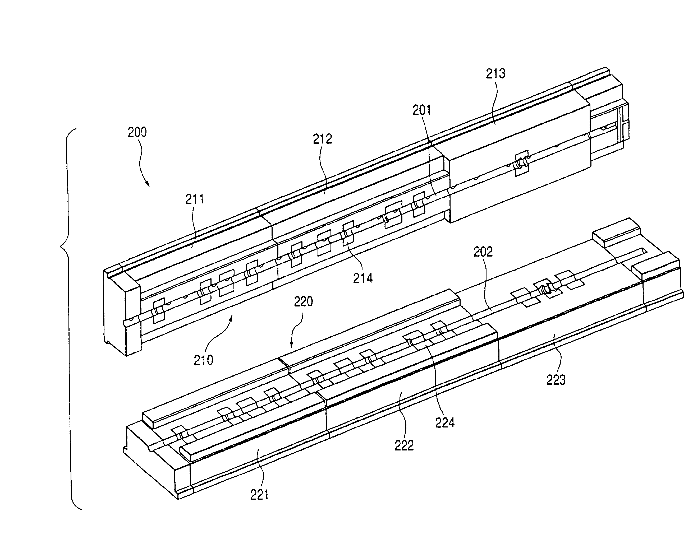
[0060]As shown in FIG. 6, in a die 200 used in molding of the shaft portion 163a of the discharging roller 163, according to the invention, cavity portions 201 and 202 are formed in order to mold one shaft portion 163a of the discharging roller 163, and the die 200 comprises an upper die 210 and a lower die 220 that are divided in the radial direction of the discharging roller 163. Here, since the conventional shaft portion of the discharging roller, formed of metal is high in rigidity, distortion can be prevented by double point support structure in which both ends are supported. However, since the shaft portion 163a of the discharging roller 163 according to the invention is formed of plastics that is lower in rigidity than the metal, five point support structure in which not only the both ends but also intermediate portions are supported is adopted to prevent the distortion.

[0061]Since molding accuracy of each bore part in the shaft portion 163a of the discharging roller 163 affe...

second embodiment

[0069]Further, as the injection method, a gas injection method can be adopted. FIG. 12 shows this configuration as the invention. To a die attaching portion of an injection molding machine of this embodiment, a die 400 and a die 450 are attached. The die 400 has the similar structure as the die 200, in which cavity portions 401, 402 for molding one shaft portion 163a of a discharging roller 163 are formed. An auxiliary cavity 451 is attached to an exhaust port 404.

[0070]Under a condition that the cavity portions 401, 402 of the die 400 are heat regulated at a predetermined temperature, the predetermined amount of the melted plastic is injected from an injection port 403 of the die 400. Subsequently, the predetermined amount of gas is injected from the injection port of the die 400. Hereby, a plastic outer surface coming into contact with the inner surfaces of the cavity portions 401, 402 is quickly cooled and pressed by gas pressure from the plastic inside. Therefore, the plastic is...


PUM

PropertyMeasurementUnit
diameter Draaaaaaaaaa
diameter Ds1aaaaaaaaaa

Abstract

In order to manufacture a discharging roller which discharges a recording medium from a recording apparatus, there are a first die formed with a first recess extending in an axial direction of a shaft portion of the discharging roller, and a second die formed with a second recess extending in the axial direction. The first die and the second die are combined such that the first recess and the second recess face to form a continuous cavity. Synthetic resin is injected into the cavity to mold a bore portion of the shaft portion.

Description

[0001]This is a divisional of application Ser. No. 10 / 388,177 filed Mar. 14, 2003; the disclosure of which is incorporated herein by reference.BACKGROUND OF THE INVENTION[0002]The present invention relates to a discharging roller which discharges a recording medium on which data recording has been performed, a method of manufacturing the discharging roller, and a recording apparatus incorporating the discharging roller.[0003]An ink jet printer that is one of recording apparatuses is generally constituted so as to supply a sheet stored in a sheet feeding tray to a sheet feeding roller, transport the supplied sheet to a recording section while holding between a sheet feeding roller pair, cause a recording head to eject an ink droplet onto the sheet to perform recording, and discharge the sheet to a sheet ejection tray while holding between a discharging roller pair. Since recording on the sheet is thus performed between the discharging roller pair and the feeding roller pair, a rotary...

Claims


Application Information

Patent Timeline
Patent Type & Authority Patents(United States)
IPC IPC(8): B41J13/03B65H27/00B29C45/17B65H5/06B41J13/02
CPCB41J13/02B41J13/03B65H27/00B29C45/1711Y10T428/139B29L2031/326B65H2401/115B65H2402/10B65H2404/133B65H2404/1351Y10T428/13Y10T29/49563Y10T428/1352Y10T29/49544B29C2045/1719B65H2401/11
Inventor NODA, SATOSHIKANZAWA, TAKAOHAMAKAWA, HIROSHI
Owner SEIKO EPSON CORP
Learn More