Bidirectional flow centrifugal microfluidic devices

a centrifugal microfluidic device and bidirectional flow technology, applied in the direction of fluid speed measurement, optical light guide, positive displacement liquid engine, etc., can solve the problems of not allowing the user to redefine the relative volume of the fluid to be mixed, degree and efficiency of mixing

Inactive Publication Date: 2002-07-25
TECAN TRADING AG
View PDF27 Cites 101 Cited by
  • Summary
  • Abstract
  • Description
  • Claims
  • Application Information

AI Technical Summary

Problems solved by technology

A problem in the art is that microfluidic devices, once fabricated, do not allow the user to redefine the relativ

Method used


Image

  • Bidirectional flow centrifugal microfluidic devices
  • Bidirectional flow centrifugal microfluidic devices
  • Bidirectional flow centrifugal microfluidic devices

Examples


Embodiment Construction

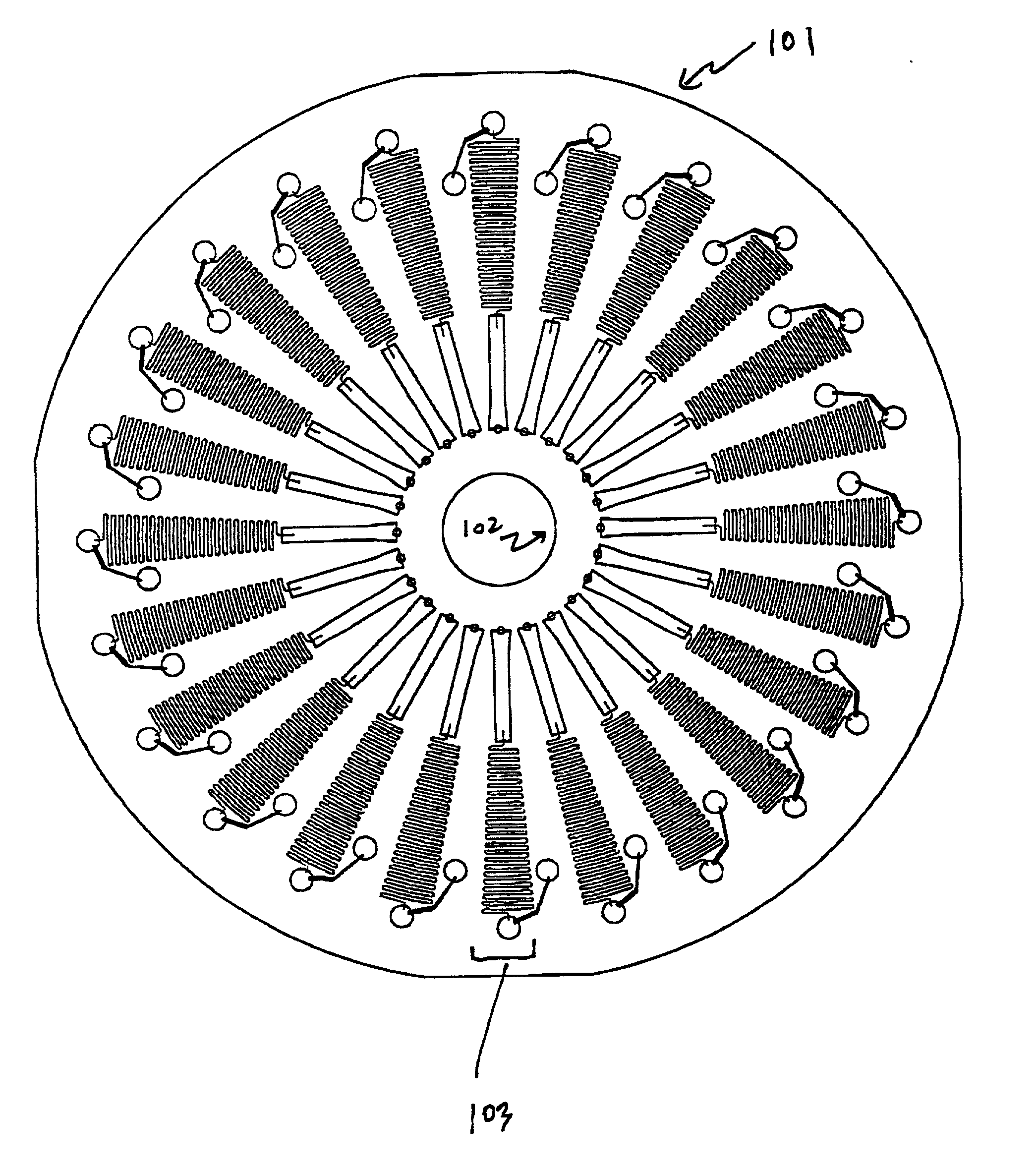
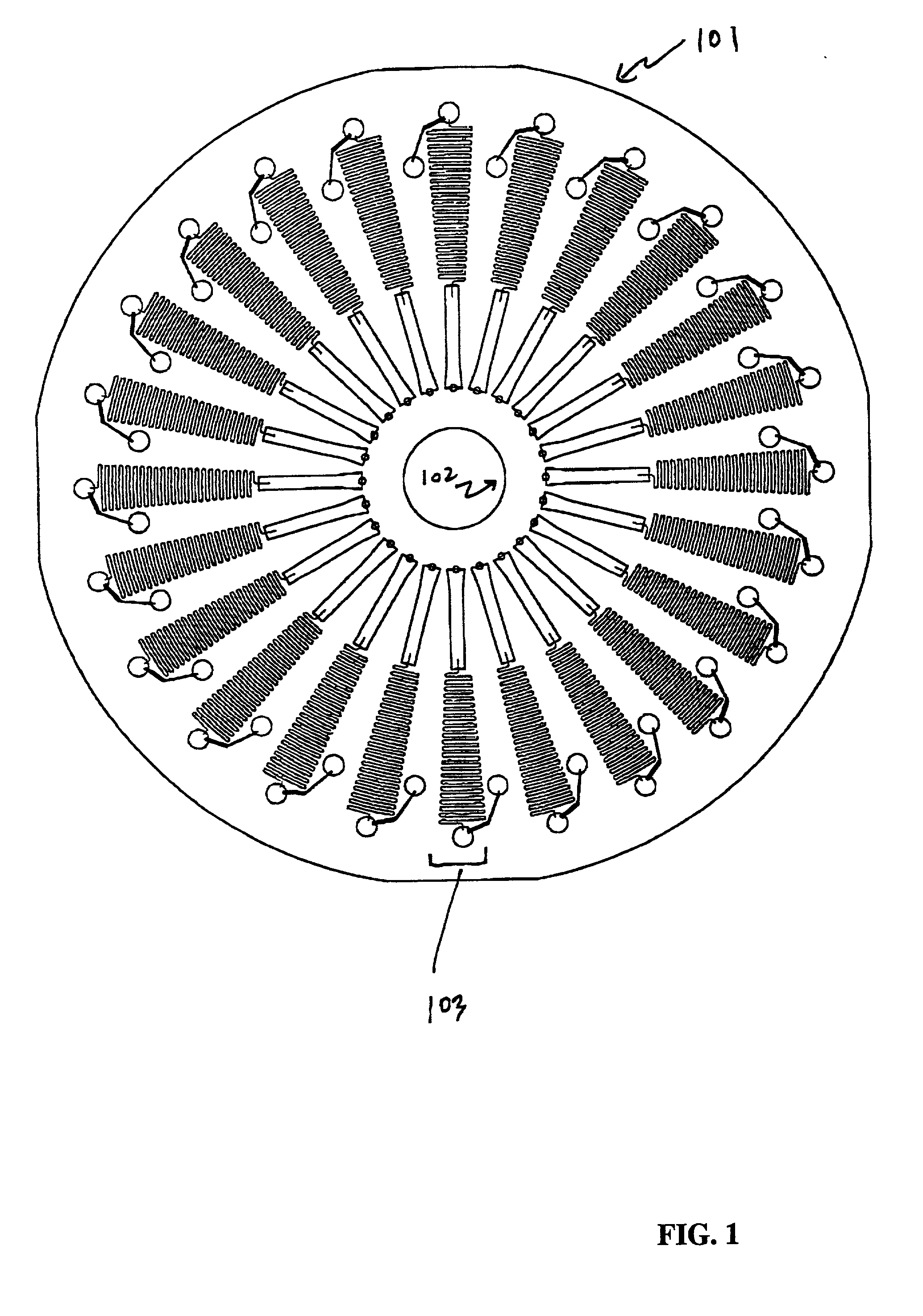
[0064] An experimental demonstration of bidirectional flow in a centrifugal microfluidic device was performed. Discs were fabricated from cast acrylic sheet (PMMA, ICI Acrylics, St. Louis, Mo.) using a computer controlled milling machine (Benchman VMC-4000, Light Machines Corp., Manchester, N.H.) and a selection of end-mills that ranged in diameter from 250 .mu.m to 1.6 mm. The machined acrylic surfaces were polished with methylene chloride vapor and then sealed with a layer of doubled-sided tape (467 MP Hi Performance Adhesive, 3M, Minneapolis, Minn.) and subsequently backed with a white polyester sheet. Liquids were pumped through the channels by rotating the discs on a spindle driven by a dc servomotor with an integral optical encoder (DC MicroMotor 3042 / HEDS-55401, MicroMo, Clearwater, Fla.). The servomotor was operated via a motor controller card (PIC-Servo, HdB Electronics, Redwood City, Calif.) and a host PC using a program written in Visual Basic (Microscoft, Redmond, Wash.)...


PUM

PropertyMeasurementUnit
Thicknessaaaaaaaaaa
Thicknessaaaaaaaaaa
Angleaaaaaaaaaa

Abstract

This invention relates to methods and apparatus for performing microanalytic and microsynthetic analyses and procedures. The invention particularly provides microsystem platforms for achieving efficient mixing of one or a plurality of fluids on the surface of the platform when fluid flow is motivated by centripetal force produce by rotation.

Description

[0001] This application claims priority to U.S. Provisional Application, Serial No. 60 / 204,264, filed May 15, 2000., the disclosure of which is explicitly incorporated by reference herein.[0002] BACKGROUND OF THE INVENTION[0003] 1. Field of the Invention[0004] This invention relates to chemical and biological assay technology carried out in disposable plastic assemblies, and in particular the devices referred to as microfluidic systems as disclosed in U.S. Pat. No. 6,063,589, issued May 16, 2000, and co-owned and co-pending patent applications U.S. Ser. No. 08 / 761,063, filed Dec. 5, 1996; Ser. No. 08 / 768,990, filed Dec. 18, 1996; Ser. No. 08 / 910,726, filed Aug. 12, 1997; Ser. No. 08 / 995,056, filed Dec. 19, 1997; and Ser. No. 09 / 315,114, filed May 19, 1999, the disclosures of each of which are explicitly incorporated by reference herein.[0005] 2. Background of the Related Art[0006] Microfluidic systems are closed interconnected networks / systems of channels and reservoirs with charact...

Claims


Application Information

Patent Timeline
IPC IPC(8): A63B63/08B01F13/00G01N21/76B01F15/02B01J19/00B01L3/00B01L7/00B81B1/00F21S2/00F21V15/04F21V33/00G01N21/05G01N21/07G01N21/78G01N35/00G01N35/02G01N37/00
CPCB01F5/0647B01F13/0059B01F15/0201B01F15/0233B01L3/5025B01L3/5027B01L3/502715B01L3/502723B01L3/50273B01L3/502738B01L7/525B01L2200/0605B01L2300/0806B01L2300/0864B01L2300/0867B01L2300/0874B01L2300/10B01L2400/0406B01L2400/0409B01L2400/0677B01L2400/0688B01L2400/088G01N21/07G01N35/00069G01N2035/00495G01N2035/00504G01N2035/00514G01N2035/00524Y10T436/111666A63B63/083B01L7/00B01L2300/1805B01F25/4331B01F33/30B01F35/71B01F35/71725
Inventor KELLOGG, GREGORY J.CARVALHO, BRUCE L.
Owner TECAN TRADING AG
Why Eureka
Try Eureka