Print system by mobile terminal, and network system using mobile terminal
- Summary
- Abstract
- Description
- Claims
- Application Information
AI Technical Summary
Problems solved by technology
Method used
Image
Examples
sixth embodiment
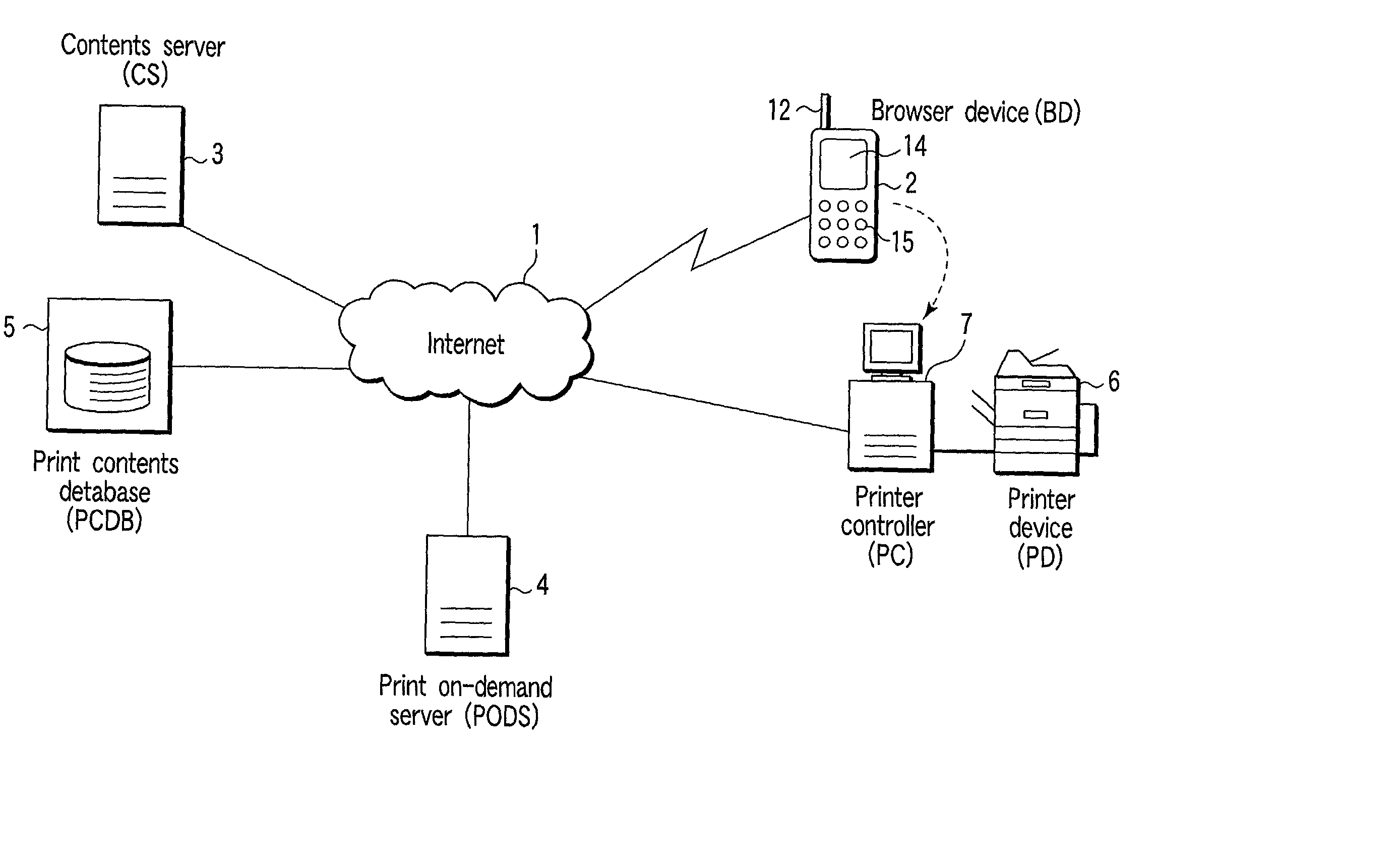
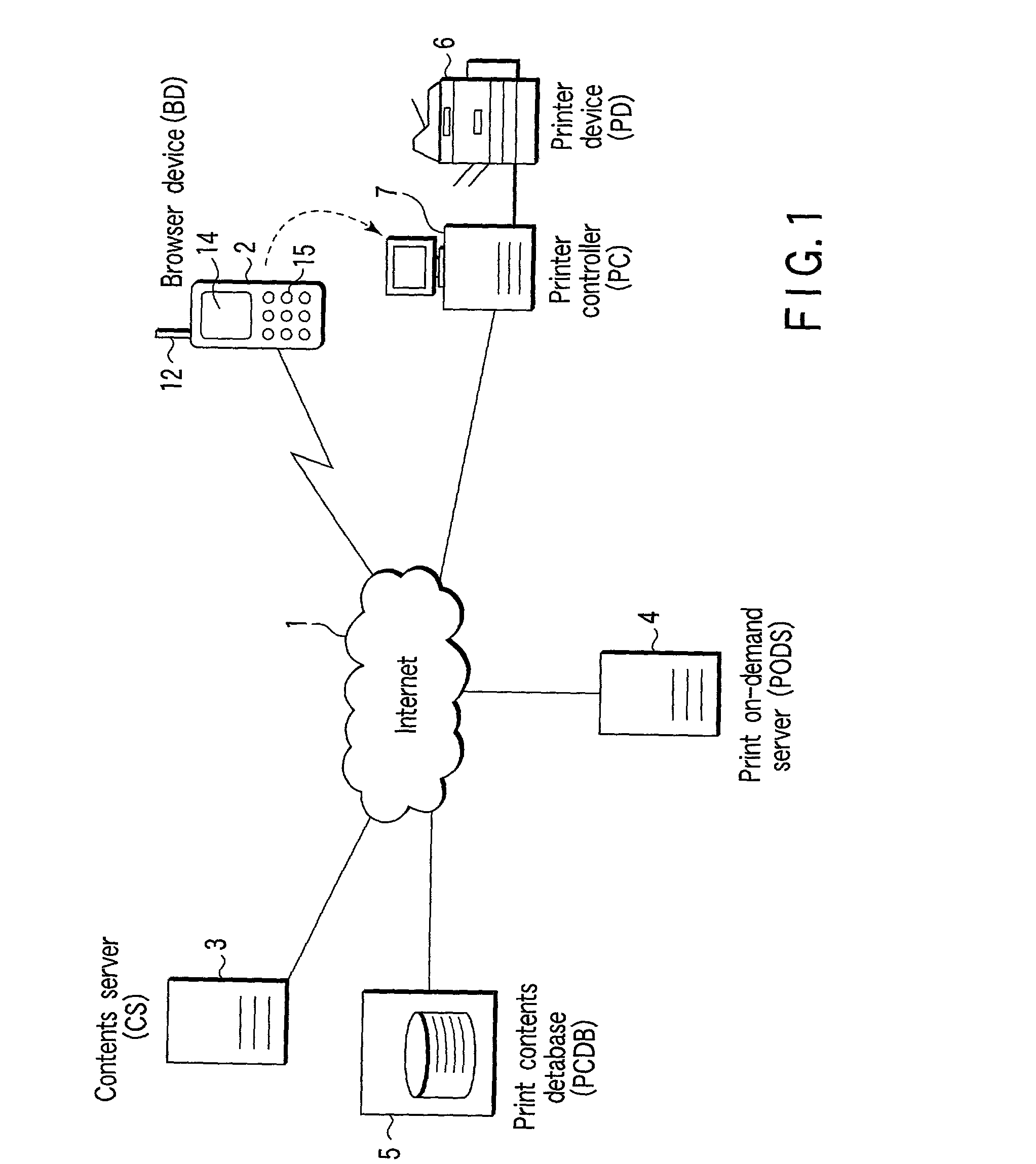
[0237] As shown in FIG. 19, in the on-demand print system of a sixth embodiment, the browser device (BD) 2 as the mobile terminal on the information reception side, the contents server (CS) 3 as the information transmission apparatus on the information transmission side, the PCDB 5 for storing the printing contents (detailed printing data, print-only data) and the printer controller (PC) 7 for controlling the printer device (PD) 6 are connected via the communication network such as Internet 1. Moreover, the BD 2 is connected to the PC 7 via radio by the Bluetooth function or via the cable. The sixth embodiment is constituted by deleting the PODS 4 from the first embodiment.
[0238] The PCDB 5 is a database for storing the printing contents (detailed printing data, print-only data), and is managed by the contents server (CS) 3 in the sixth embodiment. Thereby, the CS 3 has the registered place table 31.
[0239] An operation of the sixth embodiment will be described with reference to the ...
seventh embodiment
[0259] As shown in FIG. 21, in the on-demand print system of a seventh embodiment, the browser device (BD) 2 as the mobile terminal on the information reception side, the contents server (CS) 3 as the information transmission apparatus on the information transmission side, the PCDB 5 for storing the printing contents (detailed printing data, print-only data) and the printer controller (PC) 7 for controlling the printer device (PD) 6 are connected via the communication network such as Internet 1. Moreover, the BD 2 is connected to the PC 7 via radio by the Bluetooth function or via the cable. The seventh embodiment is constituted by deleting the PODS 4 from the first embodiment.
[0260] The PCDB 5 is a database for storing the printing contents (detailed printing data, print-only data), and is managed by the contents server (CS) 3 in the seventh embodiment. Thereby, the CS 3 has the registered place table 31.
[0261] In the seventh embodiment, the printing request from the BD 2 is transm...
eighth embodiment
[0292] As shown in FIG. 21, in the on-demand print system of an eighth embodiment, the browser device (BD) 2 as the mobile terminal on the information reception side, the contents server (CS) 3 as the information transmission apparatus on the information transmission side, the PCDB 5 for storing the printing contents (detailed printing data, print-only data), and the printer controller (PC) 7 for controlling the printer device (PD) 6 are connected via the communication network such as Internet 1. Moreover, the BD 2 is connected to the PC 7 via radio by the Bluetooth function or via the cable. The eight embodiment is constituted by omitting the PODS 4 from the first embodiment.
[0293] The PCDB 5 is a database for storing the printing contents (detailed printing data, print-only data), and is managed by the contents server (CS) 3 in the eighth embodiment. Thereby, the CS 3 has the registered place table 31. In the eighth embodiment, the printing request from the BD 2 is transmitted to ...
PUM
 Abstract
Description
Claims
Application Information
 - R&D
- Intellectual Property
- Life Sciences
- Materials
- Tech Scout
- Unparalleled Data Quality
- Higher Quality Content
- 60% Fewer Hallucinations
Browse by: Latest US Patents, China's latest patents, Technical Efficacy Thesaurus, Application Domain, Technology Topic, Popular Technical Reports.
© 2025 PatSnap. All rights reserved.Legal|Privacy policy|Modern Slavery Act Transparency Statement|Sitemap|About US| Contact US: help@patsnap.com


