Electrical wiring box

a wiring box and electrical technology, applied in the direction of electrical equipment, etc., can solve the problems of difficult and time-consuming alternate installation style, small standard electrical wiring box, and design that cannot accept electrical fittings

Inactive Publication Date: 2002-09-12
KRUER THOMAS R
View PDF0 Cites 19 Cited by
  • Summary
  • Abstract
  • Description
  • Claims
  • Application Information

AI Technical Summary

Benefits of technology

0022] FIG. 8. is a perspective view of a third embodiment of a cover to mate w

Problems solved by technology

However, standard electrical wiring boxes are smaller than a standard fired clay building brick.
This alternate style of installation is difficult and time consuming as the brick must be drilled for the wire and for mounting screws.
However, these devices are not designed to accept electrical fittings, i.e., conductors, receptacles, and switches, thereby they do not function as an electrical wiring box as the current invention.
In addition, these devices make no provision for mounting exterior electrical fixtures and lack a decorative cover to blend with the surrounding wall.
These devices merely provide a surrounding plate for lighting fi

Method used


Image

  • Electrical wiring box
  • Electrical wiring box
  • Electrical wiring box

Examples


Embodiment Construction

.

[0023] While the present invention is capable of embodiment in various forms, there is shown in the drawings and will hereinafter be described a presently preferred embodiment with the understanding that the present disclosure is to be considered as an exemplification of the invention, and is not intended to limit the invention to the specific embodiment illustrated.

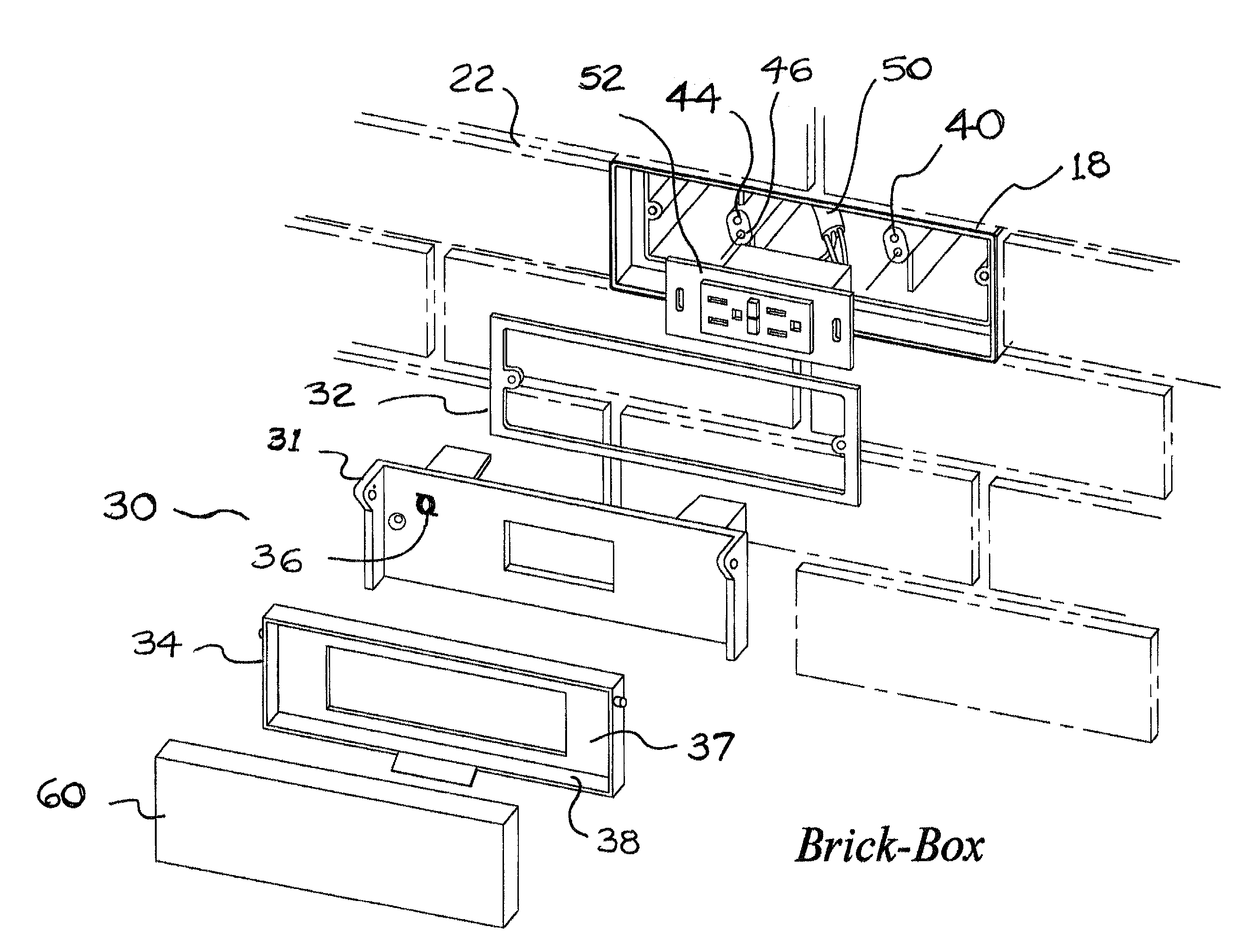
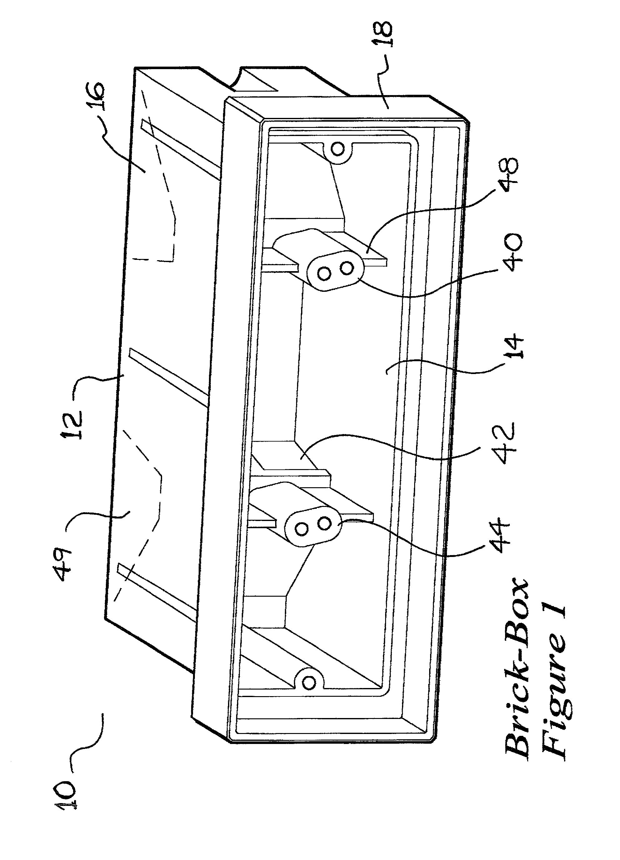
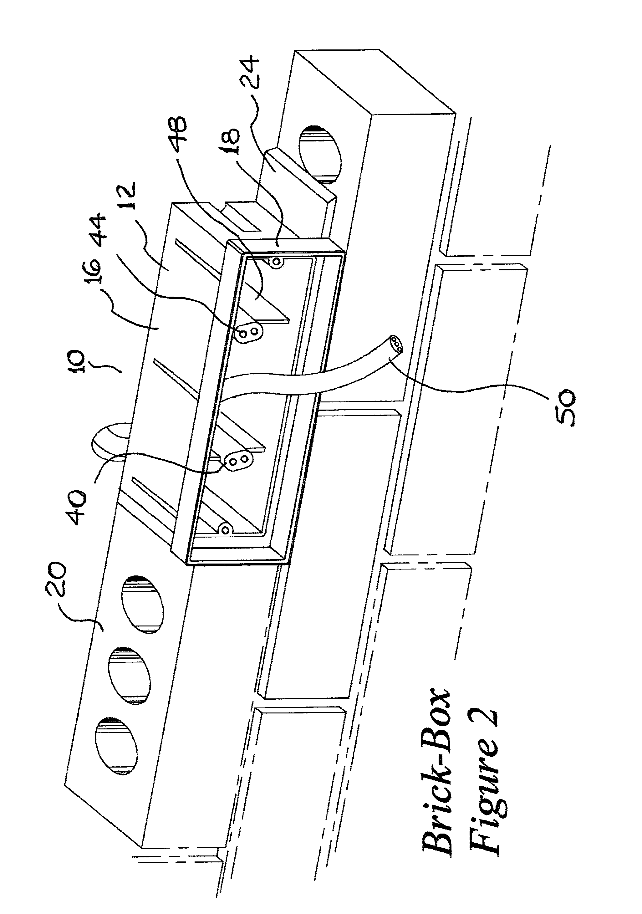
[0024] Referring now to the drawings, and more particularly to FIG. 1 and 6 which show a perspective view of an electrical wiring box generally indicated at 10 having the shape of a box 12 shaped generally as a parallelopiped with one open side 14.

[0025] The outer surfaces of the box 16 depicted are shaped and sized to match a standard building brick 20. The box 12 has an extended outer lip 18 with width matching a standard surrounding mortar joint 22. The extended outer lip 18 is used as a reference plane to position the box and to keep the mortar 24 from interfering with the installation and operation of the cover 30 ...


PUM


Abstract

An electrical wiring box with outer dimensions specifically sized and shaped to match a standard architectural component is disclosed. The disclosed electrical wiring box is of a minimum size corresponding to industrial standards and configured to accept standard electrical wires and fittings. The outer dimensions of the disclosed electrical wiring box are selectively larger than the standard box. The invention discloses an electrical wiring box which is the size of a standard fired clay building brick, or fraction thereof, thus simplifying installation in a wall of brick and mortar construction. The invention further discloses a cover which simulates a brick surface thus providing for improved appearance when installed in a brick wall. The electrical wiring box disclosed in this invention can take a number of different configurations and be used in different orientations to provide simplified installation and improved aesthetics.

Description

[0001] This invention relates to electrical wiring boxes used in construction for installation and terminating of electrical conductors. More specifically, this invention relates to electrical wiring boxes mounted within brick and mortar walls. The disclosed electrical wiring boxes may be installed in new, replacement, and remodeling applications.BACKGROUND OF INVENTION[0002] Electrical wiring boxes are typically used to terminate one or more electrical conductors and provide a secure mounting for electrical receptacles, light switches, and fixtures. They are produced in numerous standard sizes and shapes and of various materials consistent with the requirements of the application. The shapes, dimensional sizes, and materials for approved electrical wiring boxes are specified by section 314 of the 2002 Edition of the National Electric Code.[0003] Electrical wiring boxes are typically installed in new and remodeling construction wherever an electrical receptacle, light switch, or fix...

Claims


Application Information

Patent Timeline
IPC IPC(8): H02G3/12
CPCH02G3/121
Inventor KRUER, THOMAS R.
Owner KRUER THOMAS R
Why Eureka
Try Eureka