Disc transfer apparatus

a technology of transfer apparatus and disc, which is applied in the direction of data recording, instruments, information storage, etc., can solve the problems of unintentional connection of power transmission path from motor to push-back member, disc cannot be lightly inserted, and back member cannot push back disk, etc., to simplify the structure and simplify the structure. , the effect of simplifying the structur

Inactive Publication Date: 2002-09-12
TANASHIN DENKI CO
View PDF0 Cites 4 Cited by
  • Summary
  • Abstract
  • Description
  • Claims
  • Application Information

AI Technical Summary

Benefits of technology

0010] When the control gear is comprised of two coaxially integrated toothless gears, and these toothless gears are simultaneously placed opposite to the upstream and downstream gears, respectively, the structure of the apparatus can be simplified.
0011] The structure can be further simplified by forming the push-back member with an angle cam to which a cam follower is resiliently pressed to provide the toggle mechanism, and selectively positioning the cam follower on one of the inclines of the angle cam from its peak to urge the push-back member for bidirectional pivotal movements.
0012] Alternatively, a toggle spring may be extended between the push-back member and a floating chassis to constitute the toggle mechanism to further simplify the structure.
0013] In the apparatus, to control movement of a chucking mechanism into contact with and away from a turntable by a cam member which is reciprocally movably associated with the pivotal movements of the push-back member, the cam member is provided with a plurality of steps on a cam face such that the chucking mechanism is moved step by step into contact with and away from a turntable to prevent shock in a chucking operation.
0014] Further, when a sliding mechanism is interposed in the power transmission path for absorbing an overload, the sliding mechanism generates slippage to absorb the overload even if the removal of a disc is forcedly stopped, which prevents the motor from moving the pickup or the like from damaging.

Problems solved by technology

In this event, if a motor acts as a load during the insertion of the disc, the disc cannot be lightly inserted.
Therefore, if the motor is driven other than the disc removal operation, the power transmission path will be unintentionally connected by the rotating force of the motor, which causes the push-back member to push back the disk.
In other words, the disc player disclosed in Laid-open Japanese Patent Application No. 11-86401 experiences trouble in that if the disc transfer motor is used as a motor for moving a pickup (for simplifying the structure of the apparatus and reducing the manufacturing cost), the power transmission path is unintentionally connected from the motor to the push-back member when the pickup is to be moved.

Method used


Image

  • Disc transfer apparatus
  • Disc transfer apparatus
  • Disc transfer apparatus

Examples


Embodiment Construction

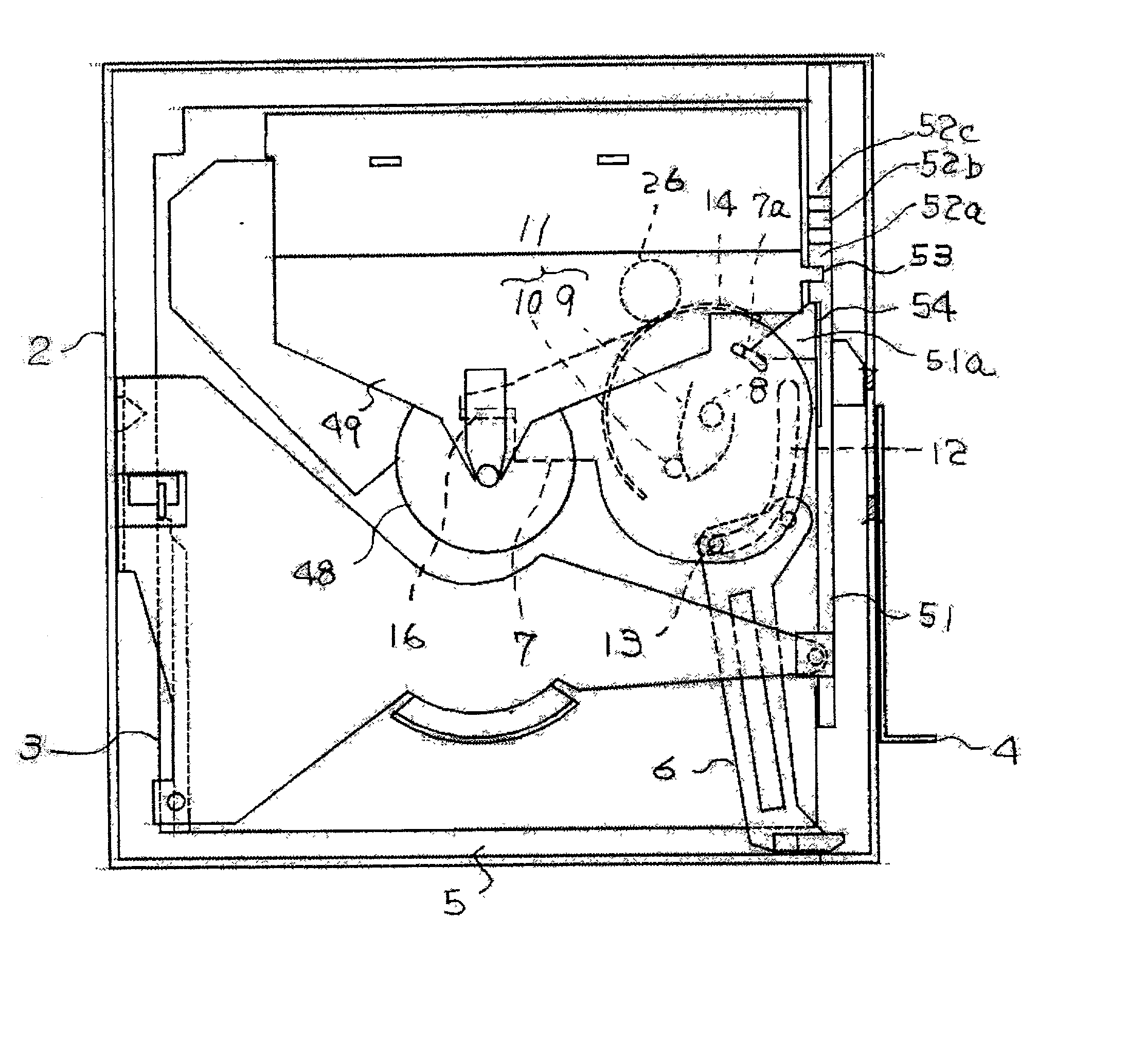
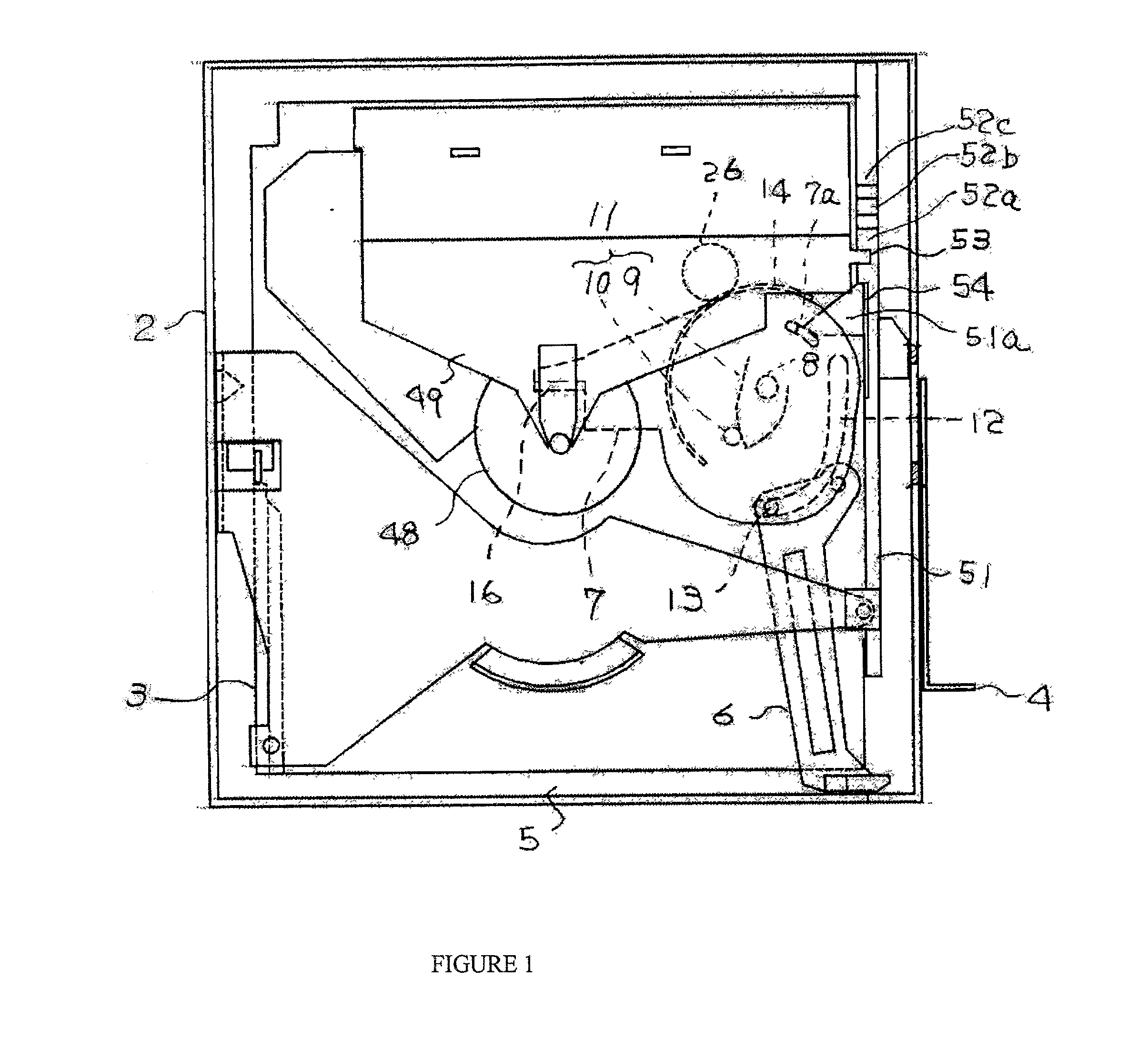
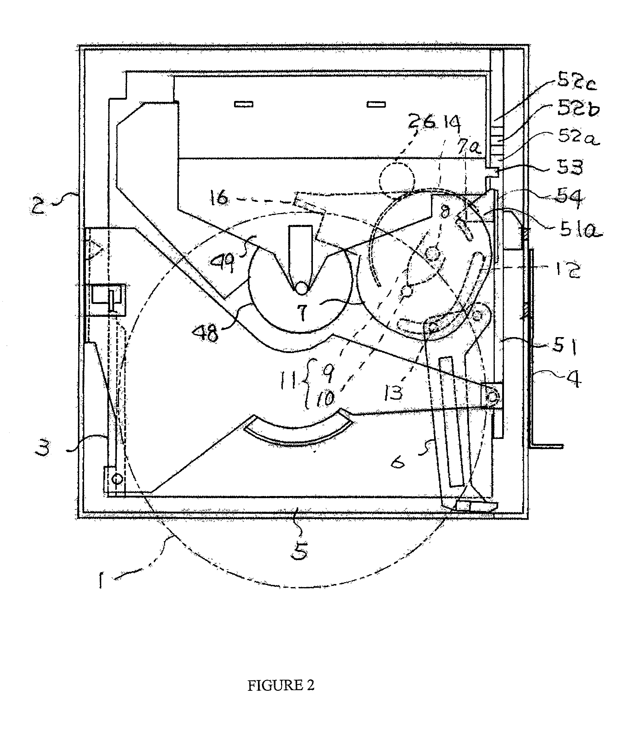
[0029] FIGS. 1 through 11 illustrate a disc transfer apparatus according to a first embodiment of the present invention.

[0030] FIGS. 1 through 3 are plan views generally illustrating a mechanism of the disc transfer apparatus, wherein FIG. 1 illustrates a state before a disc is inserted; FIG. 2 illustrates when a disc 1 is being inserted; and FIG. 3 illustrates when the disc 1 is loaded at a playing position. In a player body 2, a floating chassis 3 is resiliently supported in a floating state with respect to the body 2. Ejecting means, i.e., an eject lever 4 is mounted on an outer side of the body 2 such that the eject lever 4 is permitted to advance and retract.

[0031] The floating chassis 3 is provided with a push-in member 6 pivotally arranged for pushing the disc inserted from a disc insertion port 5 into a playing position, and a push-back member 7 pivotally arranged for pushing the disc 1 back from the playing position to the insertion port 5, respectively. The push-back membe...


PUM

PropertyMeasurementUnit
poweraaaaaaaaaa
spring forceaaaaaaaaaa
power transmissionaaaaaaaaaa

Abstract

A disc transfer apparatus which relies on a spring force for inserting a disc and on a motor for removing the disc, is provided to prevent the motor from acting as a load when the disc is inserted. A holding mechanism is provided in the disc transfer apparatus for holding a control gear included in a power transmission path (from a two ways motor for moving a pickup to a push-back member), with respect to an upstream gear and a downstream gear without meshing therewith. The control gear is released from the holding mechanism by ejecting means.

Description

BACKGROUND OF THE INVENTION[0001] 1. Field of the Invention[0002] The present invention relates an improvement in a disc transfer apparatus which relies on a spring force for inserting a disc and on a motor for removing the disc.[0003] 2. Description of the Related Art[0004] Generally, in a disc transfer apparatus, it is desired to rapidly insert a disc but relatively slowly remove the disc to prevent the disc from rushing out. Laid-open Japanese Patent Application No. 11-86401 shows a disc transfer apparatus which comprises a spring-based toggle mechanism in a disc transfer unit such that a disc is rapidly inserted with the spring force of the toggle mechanism while the disc is removed relatively slowly with the power of a motor.[0005] Specifically, a push-back member is coupled with a push-in member, and the push-back member is urged by the toggle mechanism to be pivotally moved in two opposite directions from a neutral position defined and limited by the toggle mechanism. When a ...

Claims


Application Information

Patent Timeline
Patent Type & Authority Applications(United States)
IPC IPC(8): G11B17/028G11B17/04G11B17/051
CPCG11B17/051G11B17/0515G11B17/04
Inventor TANAKA, SHINSAKUYAMANAKA, TAKASHI
Owner TANASHIN DENKI CO
Why Eureka
Try Eureka