Headrest Controlling Apparatus

a controlling apparatus and headrest technology, applied in the direction of vehicle seats, vehicle components, vehicle arrangements, etc., can solve the problems of high manufacturing cost, inability to apply the conventional stay rod, and the assembling process of the headrest in the patent document 2 is extremely complicated, so as to achieve easy assembly and operation, the effect of reducing the distan

Active Publication Date: 2020-07-09
WOOBO TECH
View PDF0 Cites 1 Cited by
  • Summary
  • Abstract
  • Description
  • Claims
  • Application Information

AI Technical Summary

Benefits of technology

[0017]The above-described headrest controlling apparatus has the following effects.
[0018]The headrest controlling apparatus includes a headrest cover, a bracket installed on a stay rod, and a locking member installed in the bracket to fix a position of a headrest, wherein the headrest cover includes a stay rod coupling part to which the stay rod is rotatably coupled, and thus can minimize a distance from the stay rod to a front lower edge of the apparatus, can be easily assembled due to the modularized bracket and locking member, can be easily operated due to increased precision of the locking member because the locking member is installed in one member (the bracket) and not separately at various members, and can reduce manufacturing costs and the entire weight due to the decreased number of components.
[0019]The stay rod coupling part includes a through hole into which the stay rod is inserted, the headrest cover is divided into a first headrest cover and a second headrest cover, and the through hole is divided and formed in the first headrest cover and the second headrest cover. Thus, the stay rod can be easily assembled to the stay rod coupling part without separation of a horizontal portion and a vertical portion of the stay rod.
[0020]The locking member includes a guide rod rotatably installed in the bracket, a sliding member slidably installed on the guide rod, and a fixing part allowing the sliding member to move or not to move on the guide rod, and the sliding member is rotatably installed in the headrest cover, and thus a structure of the apparatus can be simplified and operation can be facilitated.
[0021]The fixing part includes a notch formed in the guide rod, and a moving part slidably installed on the sliding member and having a catching part inserted into the notches, and thus a structure of the apparatus can be more simplified.
[0022]The sliding member includes a sliding groove in which the moving member slides, one of the moving member and the sliding member includes a hook, and the other one of the moving member and the sliding member has a long hole into which the hook is inserted, and thus the moving member can be easily assembled to the sliding member.

Problems solved by technology

However, the headrest-moving apparatus in Patent Document 1 should include first to fourth links because a cover is installed at the fourth link Thus, the number of components remarkably increases, and there are problems of difficult assembling, an increase in weight of the apparatus, and high manufacturing costs.
Therefore, the headrest in Patent Document 2 has an extremely complicated assembling process, cannot be applied to the conventional stay rod, and should have a thin cushion formed at a front lower edge portion of the headrest due to an increased distance from the stay rod to the front lower edge of the apparatus.

Method used


Image

  • Headrest Controlling Apparatus
  • Headrest Controlling Apparatus
  • Headrest Controlling Apparatus

Examples


first embodiment

[0046]A headrest controlling apparatus according to a first embodiment of the present invention is an apparatus for folding a headrest.

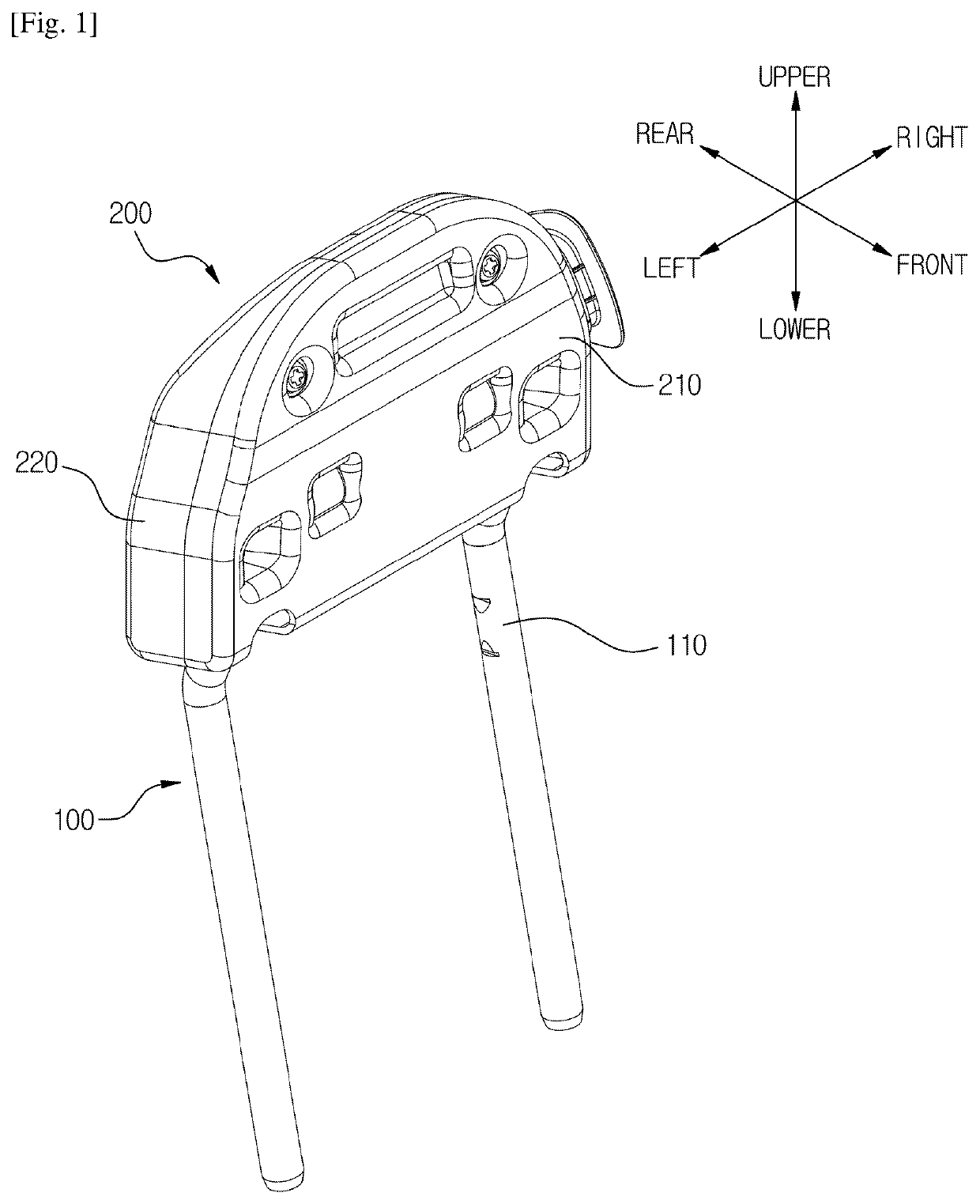
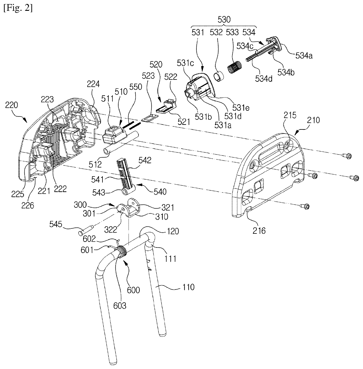
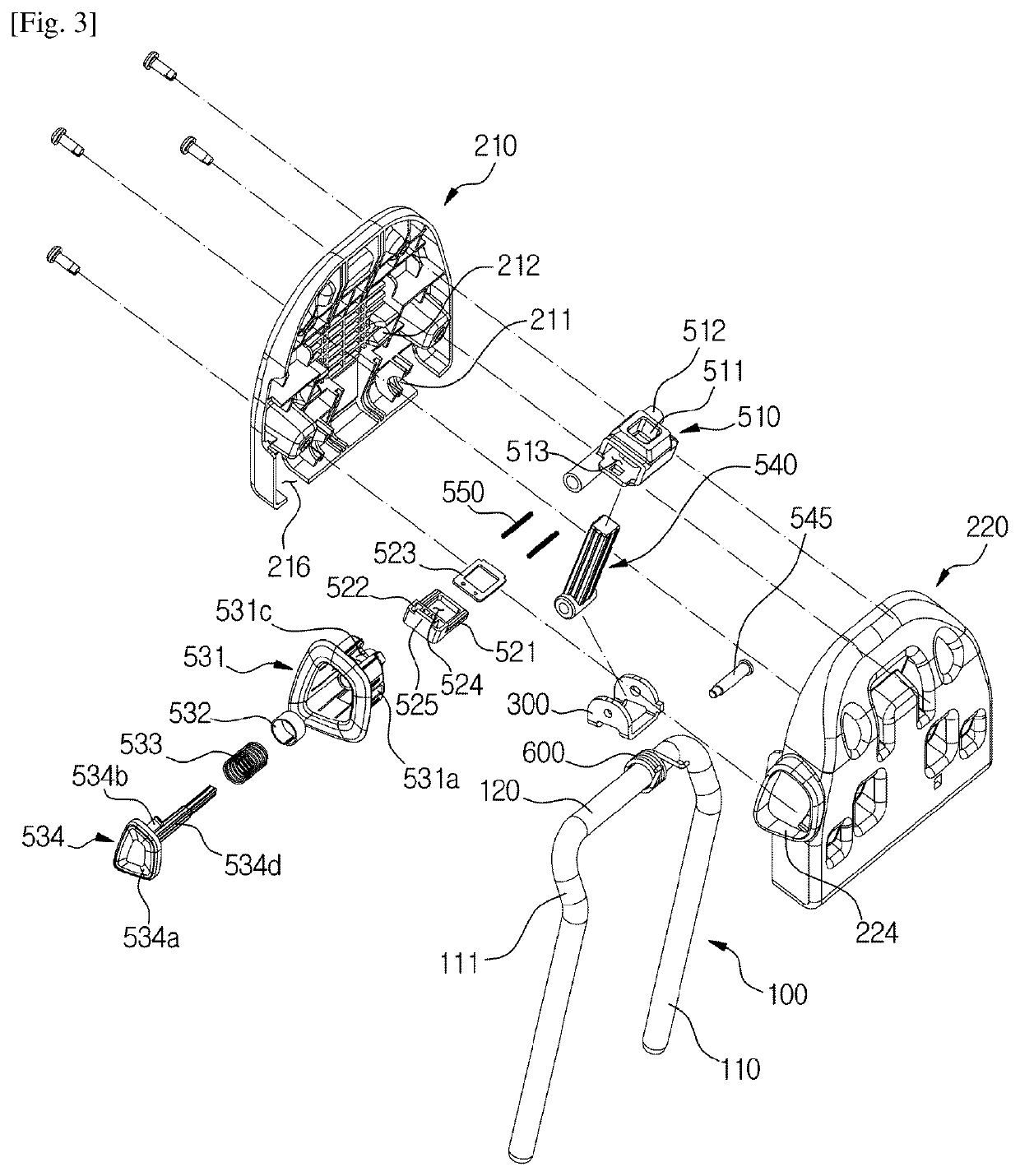
[0047]As shown in FIGS. 1 to 11, the headrest controlling apparatus of the first embodiment of the present invention includes a headrest cover 200, a bracket 300 installed on a stay rod 100, and a locking member installed in the bracket 300 to fix a position of the headrest, and the headrest cover 200 includes a stay rod coupling part to which the stay rod 100 is rotatably coupled.

[0048]Hereinafter, a width direction of a vehicle is referred to as a lateral direction, a longitudinal direction of the vehicle is referred to as a front-rear direction, and a vertical direction of the vehicle is referred to as a vertical direction. Specifically, a side adjacent to a head of a passenger is referred to as a front side, and the opposite side is referred as a rear side.

[0049]As shown in FIG. 1, the headrest cover 200 is formed to correspond to a headrest shap...

second embodiment

[0129]A headrest controlling apparatus according to a second embodiment of the present invention is an apparatus for tilting a headrest.

[0130]As shown in FIGS. 12 to 17, the headrest controlling apparatus according to the second embodiment of the present invention includes a headrest cover 1200, a bracket 1300 installed on a stay rod 100, and a locking member installed in the bracket 1300 to fix a position of the headrest. The headrest cover 1200 includes a stay rod coupling part to which the stay rod 100 is rotatably coupled, and at least three notches 1541 are formed in a guide rod 1540 of the locking member.

[0131]Detailed descriptions of the same components as those of the above-described embodiment of the invention will be omitted.

[0132]As shown in FIGS. 12 to 15, the headrest cover 1200 is divided into at least a first headrest cover 1210 and a second headrest cover 1220 disposed behind the first headrest cover 1210.

[0133]The stay rod coupling part to which a second rod 120 of ...


PUM


Abstract

The present invention relates to a headrest controlling apparatus, and more particularly, to a headrest controlling apparatus which includes a headrest cover, a bracket installed on a stay rod, and a locking member installed in the bracket to fix a position of a headrest, wherein the headrest cover includes a stay rod coupling part to which the stay rod is rotatably coupled, and thus the headrest controlling apparatus can minimize a distance from the stay rod to a front lower edge of the apparatus, can be easily assembled due to the modularized bracket and locking member, and can be easily operated due to increased precision of the locking member.

Description

TECHNICAL FIELD[0001]The present invention relates to an apparatus for controlling a position or angle of a headrest.BACKGROUND ART[0002]Generally, a vehicle headrest is installed at an upper end of a back rest of a seat to function as a pillow that comfortably supports a head of a passenger at normal times and to prevent a neck injury and the like by supporting the head not to be sharply tilted back when an accident is caused, and among conventional headrests, its position can be controlled by rotating or tilting a headrest that supports a head according to convenience of a passenger.[0003]The conventional headrests are disclosed in Korean Patent Laid-Open Publication No. 10-1171234, Korean Patent Laid-Open Publication No. 10-1044067, Korean Patent Laid-Open Publication No. 10-1071615, Korean Patent Laid-Open Publication No. 10-0982796, and the like.[0004]An apparatus for tilting a headrest is disclosed in Korean Patent Laid-Open Publication No. 10-1171234 (hereinafter, referred to...

Claims


Application Information

Patent Timeline
Patent Type & Authority Applications(United States)
IPC IPC(8): B60N2/838B60N2/90
CPCB60N2/938B60N2/838B60N2/818B60N2/856B60N2/841
Inventor JEONG, HAE IL
Owner WOOBO TECH
Why Eureka
Try Eureka