Headrest moving device

a moving device and headrest technology, applied in the direction of chairs, vehicle components, vehicle arrangements, etc., can solve the problems of increased weight, increased manufacturing cost, complex manufacturing process, etc., and achieve the effect of reducing the number of components and the weight of the apparatus, reducing manufacturing cost, and simplifying the structure of the apparatus

Active Publication Date: 2020-01-30
WOOBO TECH
View PDF0 Cites 3 Cited by
  • Summary
  • Abstract
  • Description
  • Claims
  • Application Information

AI Technical Summary

Benefits of technology

[0020]According to the headrest moving device of the present invention as described above, the following effects can be obtained.
[0021]By comprising: a moving member rotatably connected to the second member; and a guide member connected to the first member and guiding the moving member and formed with the locking groove wherein the moving member is being stopped, thereby reducing the number of components significantly and the weight of the apparatus, and the manufacturing cost can be reduced, and the button becomes unnecessary therefore the structure of the apparatus becomes simplified, and the convenience of usage is enhanced since if a user presses one time, the headrest is positioned in a first position and if presses one more time in the same way the headrest is positioned in a second position.
[0022]The second member is provided with a first stopping portion on which the first portion of the guide member is stopped and a second stopping portion on which the second portion of the guide member is stopped, so that when the user moves to fold the headrest, it is possible to protect the apparatus by not moving the headrest excessively when the user moves to fold the headrest, and the second member is supported by the guide member when the headrest is in the upright state, so that the upright state is stably maintained and a separate structure for maintaining the upright state is not required, thereby simplifying the structure.
[0023]A moving member spring that returns the moving member is further provided so that the moving member is more stably guided by the guide member.
[0024]The second member is rotatable with respect to the first member; a rod inserting hole wherein a rod is inserted is formed in the guide member; a groove is formed in the guide member along the lengthwise direction of the rod so as to be disposed inside the rod inserting hole; and a protrusion being inserted into the groove is formed in the outer circumferential surface of the rod, so that the guide member is not moved along the front-to-rear direction with respect to the rod, thereby not requiring additional process such as welding.
[0025]In the outer circumferential surface of the rod, a flange disposed at the end of the protrusion is formed so that the left-to-right movement of the guide member with respect to the rod can be prevented by a simple process like pushing the protrusion towards the guide member after inserting the rod into the guide member.

Problems solved by technology

The headrest folding device of the prior art has the manipulating button 65 to release the fixing of the cam bracket 61, thus, the number of components is increased so that the weight is increased, and since the manipulating button 65 should be exposed towards the outside of the headrest, there are problems in that the manufacturing process becomes complex and the manufacturing cost also increases.

Method used


Image

  • Headrest moving device
  • Headrest moving device
  • Headrest moving device

Examples


embodiment 1

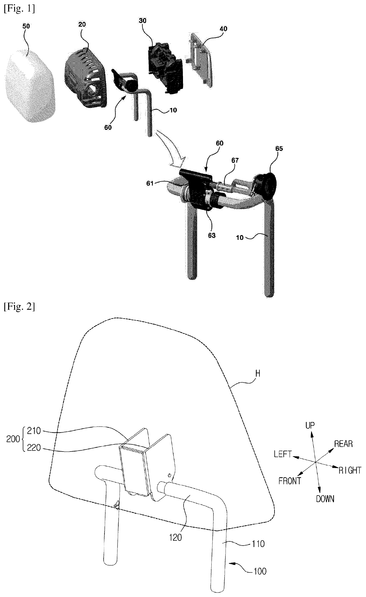
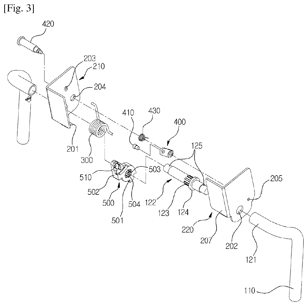
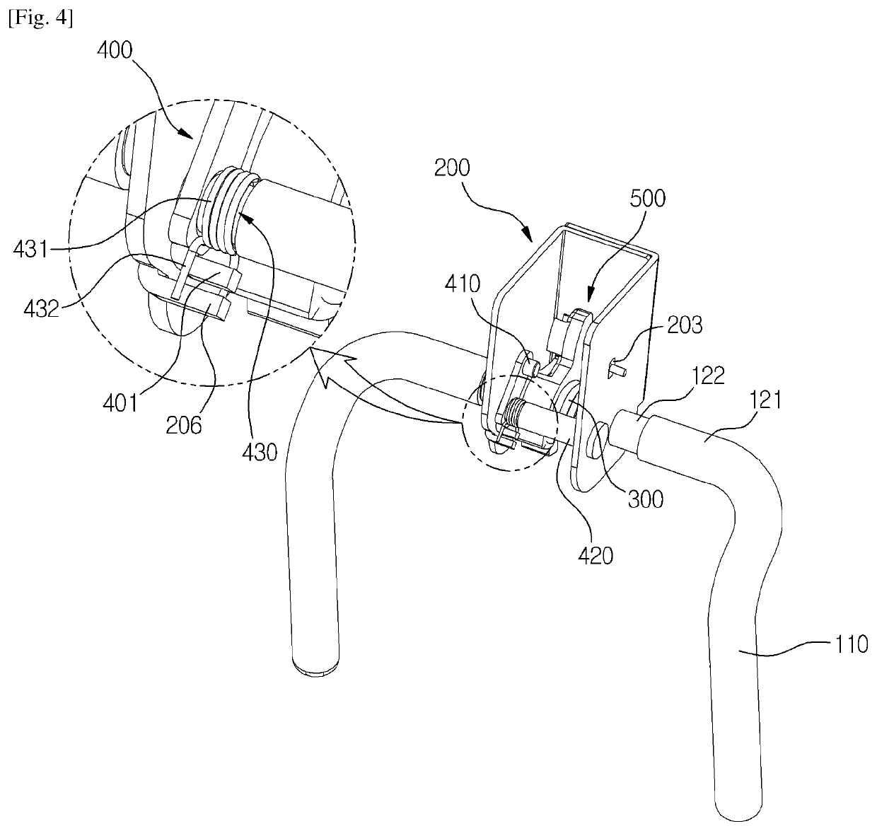
[0049]As illustrated in FIGS. 2 to 8, a headrest moving device of the present exemplary embodiments is characterized in that and comprises: a first member 100; a second member 200 capable of rotating or sliding with respect to the first member 100; a return spring 300 for returning the second member 200 with respect to the first member 100; a moving member 400 rotatably connected to the second member 200; and a guide member 500 connected to the first member 100 for guiding the moving member 400 and formed with a locking groove 513 wherein the moving member 400 is stopped.

[0050]In the present exemplary embodiment, the first member 100 is a stay rod, and the second member 200 is a bracket. Unlike to this, the first member may be a bracket and the second member may be a stay rod.

[0051]The first member 100 is fixed along the front-to-rear direction with respect to the seat, and not being moved with respect to the seat. That is, the first member 100 is connected to the seat.

[0052]The sec...

embodiment 2

[0142]In describing the headrest moving device according to the second exemplary embodiment of the present invention, same symbols will be used for the same or similar elements as those of the headrest moving device according to the previous exemplary embodiment of the present invention, and the detailed description and illustration will be omitted.

[0143]As illustrated in FIGS. 9 and 10, the headrest moving device according to the second exemplary embodiment is locked as a moving member 400 is inserted into a locking groove 513 of a guide member 500′ when the headrest is in an upright state, and the guide member 500′ is installed in a first member 100 in a way that the moving member 400 is separated from the locking groove 513 when the headrest is in a folded state.

[0144]The elastic force of the return spring is applied clockwise to a second member 200 wherein the moving member 400 is rotatably mounted.

[0145]A first portion 501′ in which a first stopping portion 201 is stopped is di...

embodiment 3

[0151]In describing the headrest moving device according to the third exemplary embodiment of the present invention, same symbols will be used for the same or similar elements as those of the headrest moving device according to the previous exemplary embodiments of the present invention, and the detailed description and illustration will be omitted.

[0152]As illustrated in FIGS. 12 to 14, a first member 100′ of the headrest moving device according to the third exemplary embodiment of the present invention is connected to the headrest, and a second member 200′ is connected to the seat.

[0153]The headrest is provided on the upper side of a vertical portion 110 of the first member 100′. A horizontal portion 120 is disposed at the lower side of the vertical portion 110. A guide member 500″ is provided on the horizontal portion 120. A first portion 501″ of the guide member 500″ is disposed at the rear upper of the second portion 502″. A guide pathway formed in the guide member 500″ at the ...


PUM


Abstract

The present invention relates to a headrest moving device, more particularly, relates to a headrest moving device comprising: a moving member rotatably connected to a second member; and a guide member connected to the first member and guided by the first member and having a locking groove formed therein for guiding the moving member so that the number of parts of the device is significantly reduced, the weight of the apparatus can be reduced, the manufacturing cost of the apparatus can be reduced, the structure of the apparatus can be simplified since the button can be omitted, and the convenience of usage is enhanced since if a user presses one time, the headrest is positioned in a first position and if presses one more time in the same way the headrest is positioned in a second position.

Description

TECHNICAL FIELD[0001]The present invention relates to a headrest moving device, more particularly, relates to a headrest moving device comprising a moving member rotatably connected to a second member, and a guide member connected to a first member for guiding the moving member and formed with a locking groove wherein the moving member is stopped.BACKGROUND ART[0002]A headrest folding device of the prior art, as illustrated in FIG. 1, comprises: a folding frame 10 formed in the shape of a pole in the upper side of a seat so as to be pulled out, the folding member 10 mounted with a folding means 60 at the end thereof; a front housing 20 and a rear housing 30 mutually coupled to each other and protecting the folding means 60 of the folding frame 10; a rear cover 40 covering the rear-side of the rear housing 30; and a pad 50 provided in the outer side surface of the front housing 20 and supporting the back of the passenger's head.[0003]At this time, the folding means 60 is provided wit...

Claims


Application Information

Patent Timeline
Patent Type & Authority Applications(United States)
IPC IPC(8): B60N2/847A47C7/38B60N2/844B60N2/856B60N2/853
CPCB60N2/847B60N2/853A47C7/38B60N2/856B60N2/844B60N2/841
Inventor JEONG, HAE IL
Owner WOOBO TECH
Why Eureka
Try Eureka