Electrostatic deflection control circuit and method of electronic beam measuring apparatus

Active Publication Date: 2007-03-22
HITACHI HIGH-TECH CORP
View PDF2 Cites 4 Cited by
  • Summary
  • Abstract
  • Description
  • Claims
  • Application Information

AI Technical Summary

Benefits of technology

[0012] According to the electrostatic deflection circuit and method of the electronic beam measuring apparatus of the present invention, it is possible to achieve the high precision of the electronic beam measuring and to con

Problems solved by technology

For this reason, there has been a problem that it is difficult to obtain an image of high precision or high magnification because the center of the field of vision is shifted with the change of the scan magnification or the aberration such as a distortion is generated on the beam.
Also, as it is provided with two kinds of deflectors there have been problems that it is difficult to mechanically match the light axes of the deflectors each other, moreover, that the structure of the entire deflector would be complicated, large, and expensive.
For this reason, compared with an apparatus provided with a single deflector, th

Method used


Image

  • Electrostatic deflection control circuit and method of electronic beam measuring apparatus
  • Electrostatic deflection control circuit and method of electronic beam measuring apparatus
  • Electrostatic deflection control circuit and method of electronic beam measuring apparatus

Examples


Example

[0021] Next, an embodiment of the present invention will be explained in detail referring to the drawings.

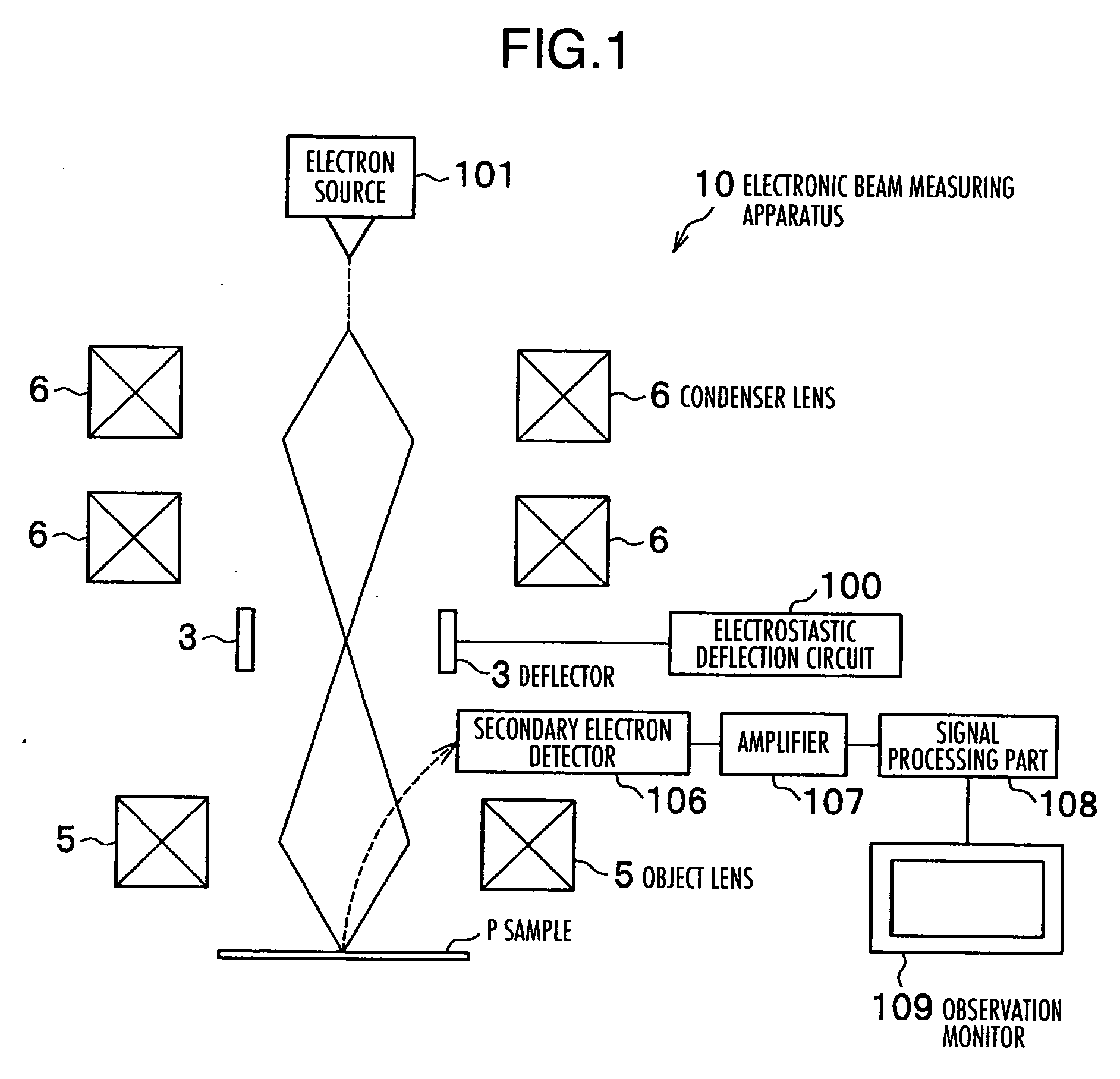
[0022]FIG. 1 is a principle structure diagram of an electronic beam measuring apparatus 10 according to an embodiment of the present invention.

[0023] The electronic beam measuring apparatus 10 is typically a scanning electron microscope (SEM) or such an apparatus provided with an additional function.

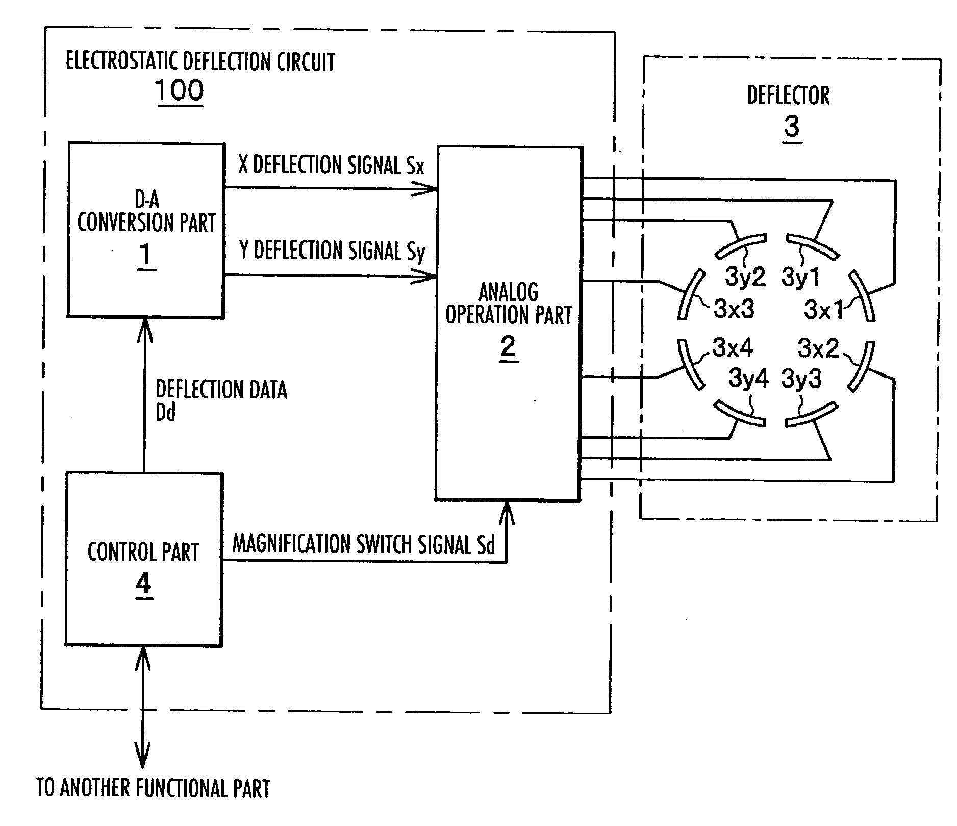
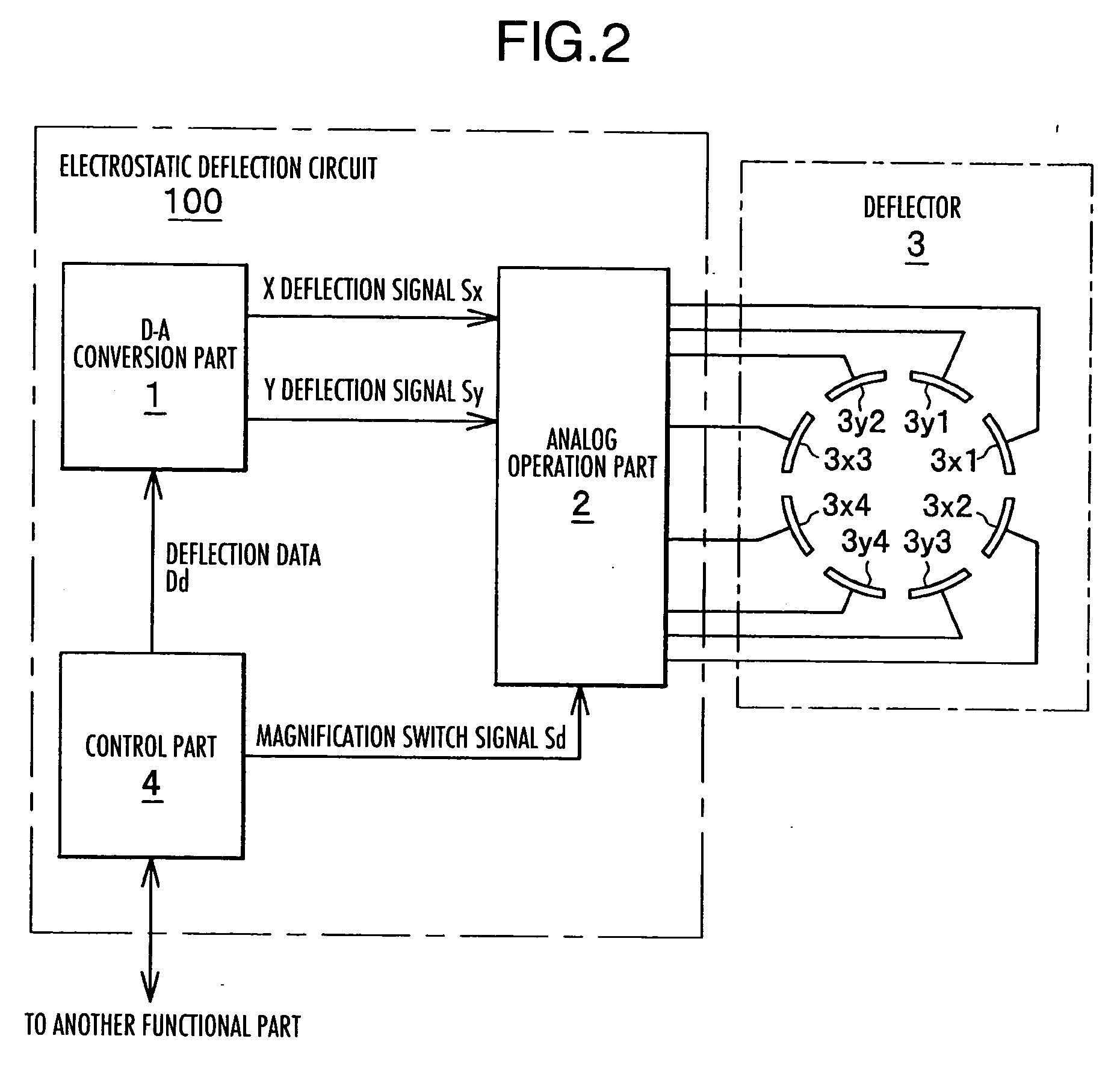
[0024] More specifically, the electronic beam measuring apparatus 10 is provided with an electron source 101 which generates an electron beam (electronic beam), a condenser lens 6 which once converges the electronic beam generated at the electron source 101, a deflector 3 which deflects the electronic beam by generating an electrostatic field, an electrostatic deflection circuit (corresponding to an “electrostatic deflection circuit” stated in the claims) 100 which supplies a deflection voltage to the deflector 3, an object lens 5 which focuses the electronic beam on a sample P by...


PUM


Abstract

An electrostatic deflection circuit and method of an electronic beam measuring apparatus which can achieve the high precision of the electronic beam measuring and contribute to the simplification of the structure of the apparatus is provided. In an analog arithmetic circuit included in an analog operation part constituting an electrostatic deflection circuit, output voltages of multipliers are added and output by an adder. When the magnification is low, as the side of an ordinarily closed contact is closed driven by a relay driving circuit, the output of the adder is amplified by a high gain amplifier with a high amplification factor and applied to an electrostatic deflecting board. When the magnification is high, the side of an ordinarily open contact is closed and it is amplified by a low gain amplifier with a low amplification factor and applied to the electrostatic deflecting board in the same way.

Description

INCORPORATION BY REFERENCE [0001] The present application claims priority from Japanese application JP2005-270660 filed on Sep. 16, 2005, the content of which is hereby incorporated by reference into this application. BACKGROUND OF THE INVENTION [0002] The present invention relates to an electrostatic deflection circuit and method for controlling the deflection of an electronic beam in an electronic beam measuring apparatus which scans a sample by an electron beam (electronic beam) and measures minute patterns. [0003] The electronic beam measuring apparatus such as a scanning electron microscope generates an electronic beam from an electron gun and converges it on a sample, and at the same time applies a force on this electronic beam using a deflector, scans on the sample by deflecting irradiation points and collects information of the sample, and it is used, for example, for the check of the minute circuit patterns, etc. [0004] The electronic beam measuring apparatus is generally r...

Claims


Application Information

Patent Timeline
IPC IPC(8): H01J37/147
CPCH01J37/24H01J2237/2814H01J2237/1516
Inventor SASAKI, HIROSHI
Owner HITACHI HIGH-TECH CORP
Why Eureka
Try Eureka