Ignition device, particularly for an atomizer burner of a motor vehicle heating appliance

a technology for atomizer burners and heating appliances, which is applied in vehicle heating/cooling devices, combustion processes, vehicle components, etc., and can solve problems such as the inability to produce glow ignition components

Inactive Publication Date: 2002-09-12
EBERSPAECHER CLIMATE CONTROL SYST GMBH & CO KG
View PDF5 Cites 16 Cited by
  • Summary
  • Abstract
  • Description
  • Claims
  • Application Information

AI Technical Summary

Benefits of technology

0007] The present invention has as its object to provide a cost-efficient igni...

Problems solved by technology

This was heretofore not possible, since the removal of heat from a glow ignition member was very great due to the flow speed of the materials injected into the combustion chamber in the...

Method used


Image

  • Ignition device, particularly for an atomizer burner of a motor vehicle heating appliance
  • Ignition device, particularly for an atomizer burner of a motor vehicle heating appliance

Examples


Embodiment Construction

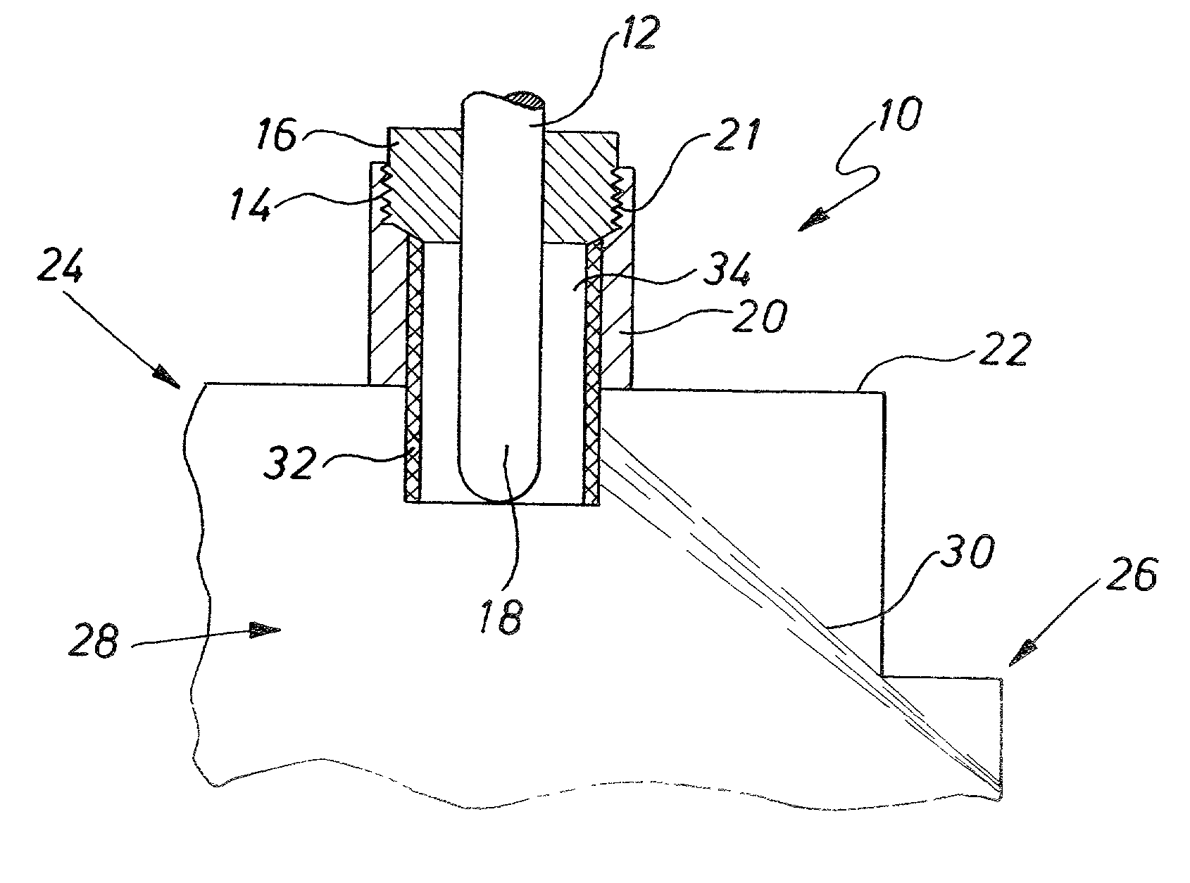
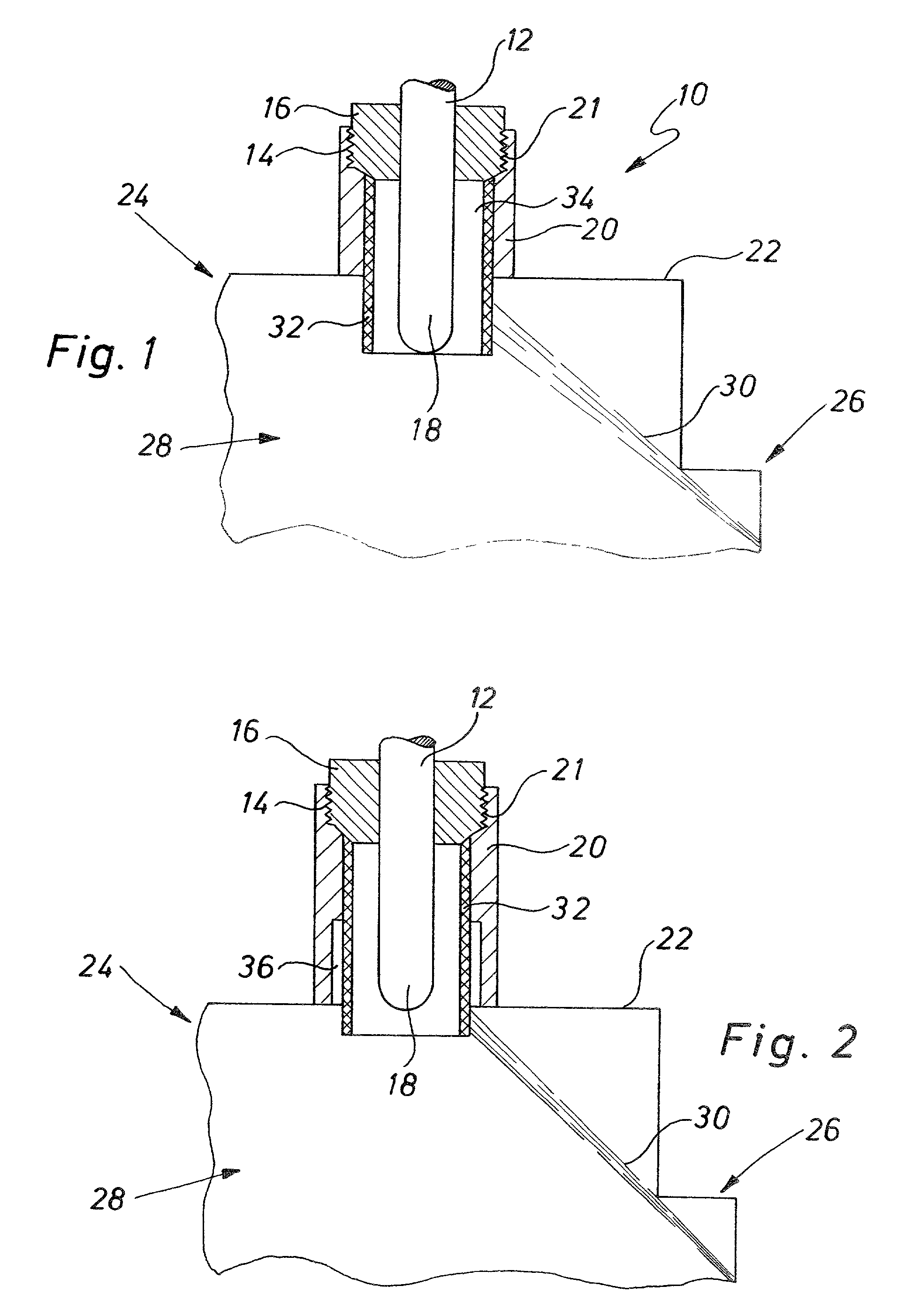
[0019] A glow ignition member is generally denoted in FIG. 1 by the numeral 10. The glow ignition member 10 comprises a glow plug or a glow pin 12 of conventional construction, which can thus have, for example, a heating coil and if necessary a control coil as well as insulating powder or the like, in a heat-resistant glow tube. The glow pin 12 is supported in a support member 16 provided with an external thread 14, and projects over this support portion 16 with its free end region 18, which for example then contains the heating coil. The support member 16 is supported in a substantially cylindrical support sleeve 20 with an internal thread 21. The support sleeve 20 can be installed on a housing 22, shown schematically, of a heating burner 24. This heating burner 24 furthermore has an atomizer nozzle 26, shown schematically. Combustion air is introduced at high speed into the combustion chamber 28 of the heating burner 24 by means of the atomizer nozzle 26. The combustion air, flowi...


PUM


Abstract

An ignition device, in particular for an atomizer burner of a motor vehicle heating appliance, comprises a glow ignition member and screening material, which can take up fuel and which surrounds the glow ignition member at least over a region.

Description

CROSS-REFERENCES TO RELATED APPLICATIONS[0001] Not applicable.STATEMENT REGARDING FEDERALLY SPONSORED RESEARCH OR DEVELOPMENT[0002] Not applicable.[0003] 1. Background of the Invention[0004] The present invention relates to an ignition device, particularly for an atomizer burner of a motor vehicle heating appliance.[0005] 2. Technical Field[0006] In heating appliances, such as are used as so-called supplementary heaters or auxiliary heaters in motor vehicles, fuel is fed together with combustion air into a combustion chamber and is combusted there. The combustion is ignited by so-called spark gaps, such as also find application in heating burners in heating installations of buildings. The spark gaps provided for ignition, as used in particular in connection with so-called atomizer burners, in which the fuel to be burned is injected together with the combustion air at high speed and thus atomized, are comparatively expensive and thus represent a not inconsiderable cost factor, partic...

Claims


Application Information

Patent Timeline
IPC IPC(8): B60H1/03F23Q7/08F23Q7/06F23Q7/22
CPCF23Q7/001F23Q7/22
Inventor EBERSPACH, GUNTERBLASCHKE, WALTER
Owner EBERSPAECHER CLIMATE CONTROL SYST GMBH & CO KG
Why Eureka
Try Eureka