Method for fabricating cladding layer in top conductor

a top conductor and cladding technology, applied in the direction of digital storage, instruments, semiconductor devices, etc., can solve the problems of reducing the size of the memory cell, increasing the field required to switch the orientation, reducing the dimensions of the word and bit lines, etc., to prevent the disruption of the magnetization effect and enhance the write field

Inactive Publication Date: 2002-09-12
SAMSUNG ELECTRONICS CO LTD
View PDF0 Cites 42 Cited by
  • Summary
  • Abstract
  • Description
  • Claims
  • Application Information

AI Technical Summary

Benefits of technology

[0009] It has been recognized that it would be advantageous to develop a magnetic memory with write conductors that produce enhanced write fields. In addition, it has been recognized that it would be advantageous to develop a magnetic memory with flux closure structures that prevent disruptions to magnetization. In addition, it has been recognized that it would be advantageous to develop a method to fabricate such conductor structures. To this end, it has been recognized that it would be advantageous to clad the top conductors of the magnetic memory.

Problems solved by technology

Reducing the size of the memory cell, however, increases the field required to switch the orientation of the magnetization of the sense layer.
Reducing the dimensions of the word and bit lines, however, reduces the current that can be accommodated thereby, and thus the magnetic field at the corresponding magnetic bit region.
However, this increases the possibility that the magnetic field produced by one line way adversely affect the information stored in an adjacent memory cell.

Method used


Image

  • Method for fabricating cladding layer in top conductor
  • Method for fabricating cladding layer in top conductor
  • Method for fabricating cladding layer in top conductor

Examples


Embodiment Construction

[0018] For the purposes of promoting an understanding of the principles of the invention, reference will now be made to the exemplary embodiments illustrated in the drawings, and specific language will be used to describe the same. It will nevertheless be understood that no limitation of the scope of the invention is thereby intended. Any alterations and further modifications of the inventive features illustrated herein, and any additional applications of the principles of the invention as illustrated herein, which would occur to one skilled in the relevant art and having possession of this disclosure, are to be considered within the scope of the invention.

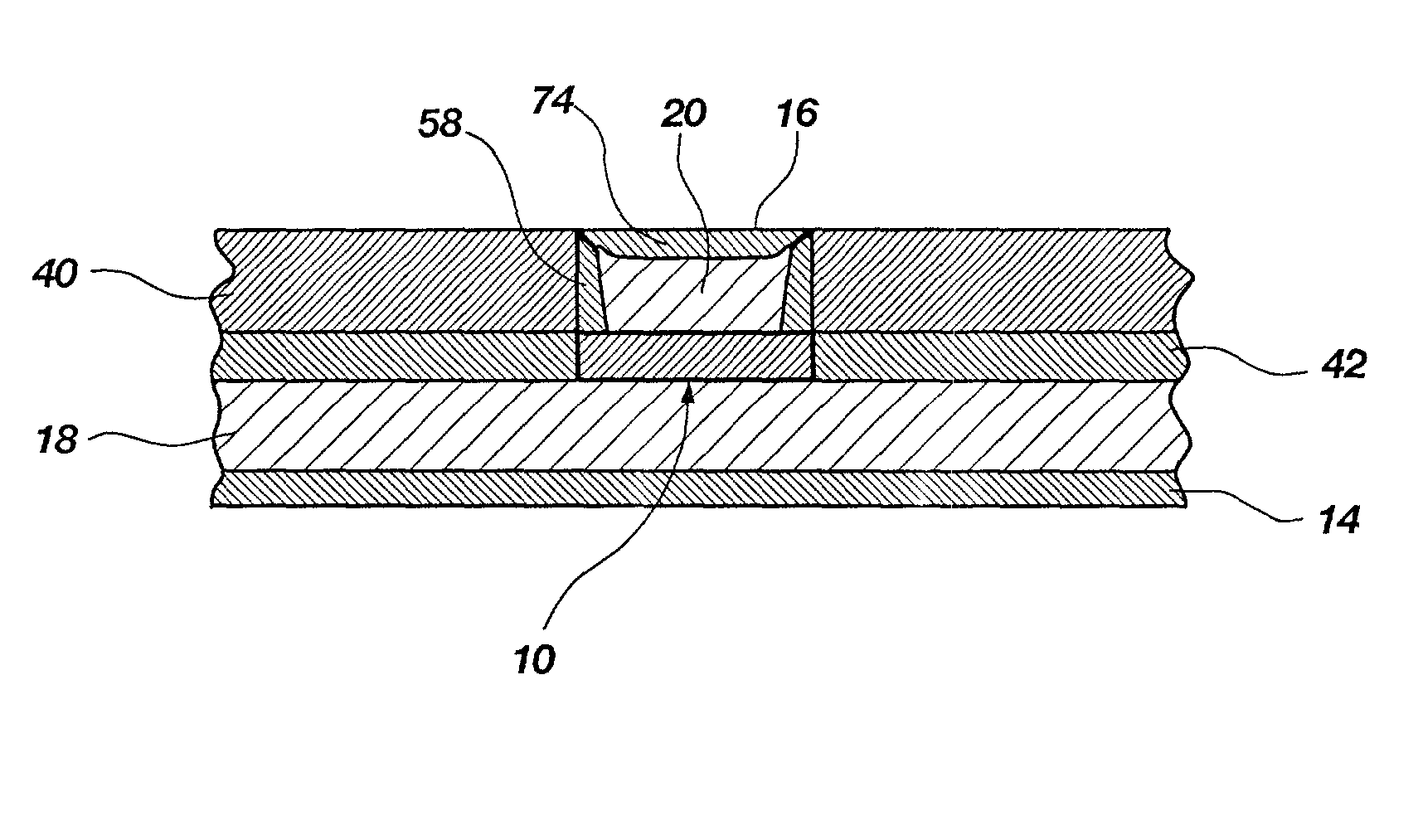
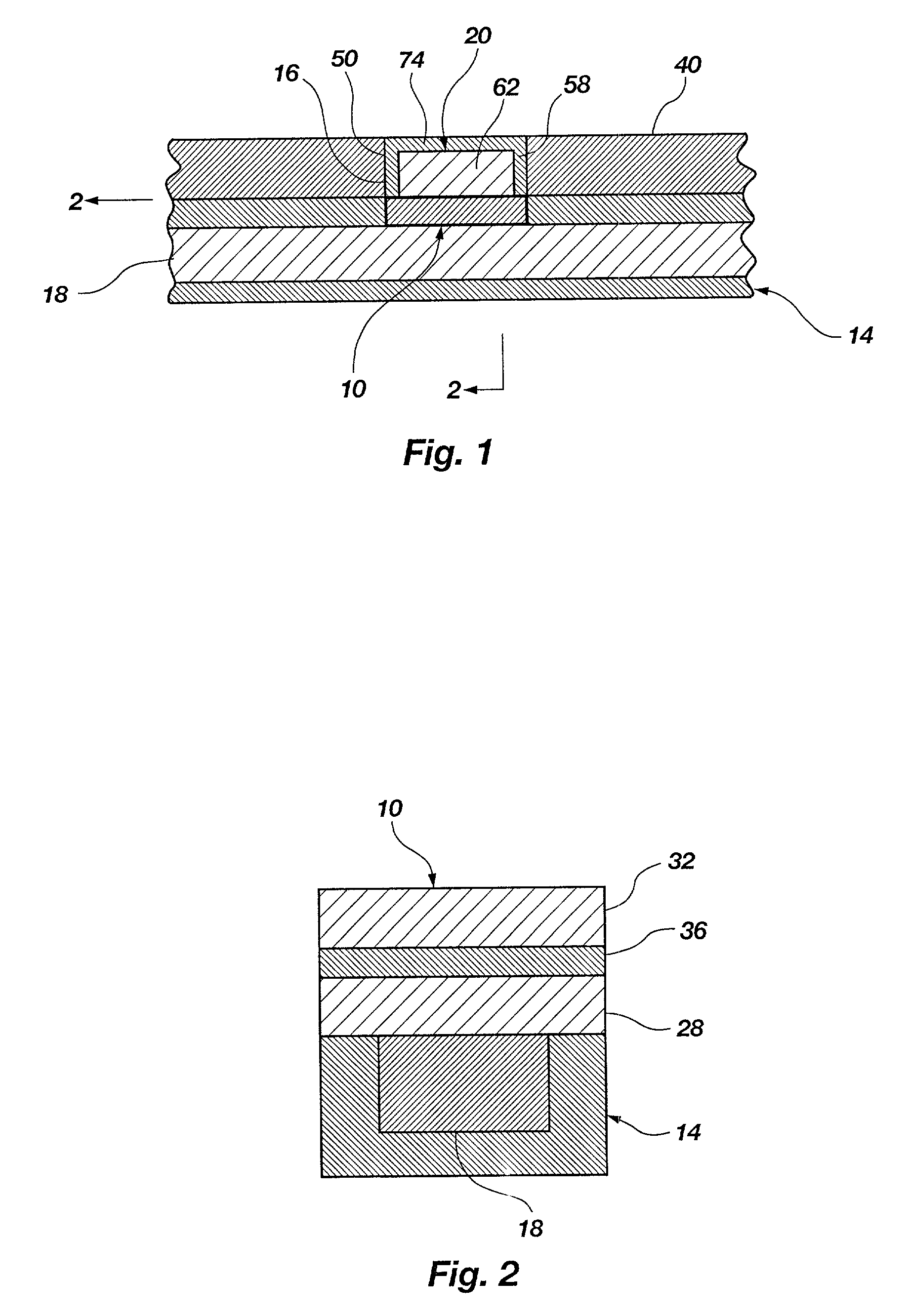
[0019] As illustrated in FIGS. 1 and 2, a conventional magnetic memory device or cell, or a portion of a magnetic RAM structure, indicated generally at 10, is shown with bottom and top structures or cladding 14 and 16 for enhancing the write field and / or stabilizing the magnetic memory cell 10. The structures 14 and 16 encase bott...


PUM


Abstract

A method for cladding two or three sides of a top conductor for a magnetic memory device in ferromagnetic material includes forming a trench with side walls in a coating layer above the memory device. A first ferromagnetic material is deposited along the side walls of the trench. Any ferromagnetic material in a bottom of the trench can be removed. A conductor material is deposited in the trench over the memory device. A second ferromagnetic material is deposited over the conductor material in the trench to form a cladding of the ferromagnetic material around three sides of the conductor.

Description

BACKGROUND OF THE INVENTION[0001] 1. The Field of the Invention[0002] The present invention relates generally to a method for forming a cladding layer in a top conductor, particularly useful with magnetic RAM structures, and a magnetic memory device having a cladding structure about the top conductor.[0003] 2. The Background Art[0004] A magnetic memory, such as a magnetic random access memory (MRAM), typically includes an array of magnetic memory cells. Each magnetic memory cell usually includes a sense layer and a reference layer. The sense layer is usually a layer or film of magnetic material that stores magnetization patterns in orientations that may be altered by the application of external magnetic fields. The reference layer is usually a layer of magnetic material in which the magnetization is fixed or "pinned" in a particular direction. The magnetic memory can be described as including a number of bit lines intersected by a number of word lines. At each intersection, a thin f...

Claims


Application Information

Patent Timeline
Patent Type & Authority Applications(United States)
IPC IPC(8): G11C11/15G11C11/16H01L21/8246H01L27/105G11C11/14H01L27/22H01L43/08
CPCB82Y10/00G11C11/161H01L27/222H10B61/00G11C11/15
Inventor NICKEL, JANICE H.ANTHONY, THOMAS C.
Owner SAMSUNG ELECTRONICS CO LTD
Why Eureka
Try Eureka